Installation Procedure
| Required Tools | |||
| Tool | Part Number | Description | Qty |
| B | 138-7573 | Link Bracket | 2 |
Note: Inspect all O-ring seals before beginning the installation. Replace any O-ring seals that are worn or damaged.
Note: Refer to the Specifications Manual, “RENR5843” for special torques that are required.
|
|
| NOTICE |
|---|
|
Care must be taken to ensure that fluids are contained during performance of inspection, maintenance, testing, adjusting and repair of the product. Be prepared to collect the fluid with suitable containers before opening any compartment or disassembling any component containing fluids. Refer to Special Publication, NENG2500, “Caterpillar Tools and Shop Products Guide” for tools and supplies suitable to collect and contain fluids on Caterpillar products. Dispose of all fluids according to local regulations and mandates. |
|
|
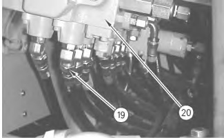
- Install Tooling (B) and a suitable lifting device on control valve (20). Position the control valve in the machine. The main control valve weighs approximately 91 kg (200 lb).
|
|
|
|
|
|
| Illustration 1 | g00910454 |
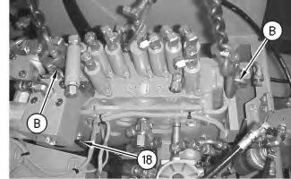
- Install bolts (18) in order to secure the control valve in the machine.
- Remove Tooling (B) from the control valve.
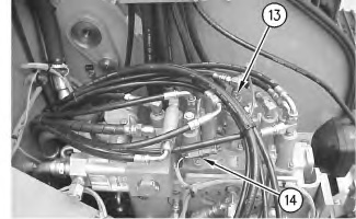
- Connect hose assemblies (13) to the top of the control valve.
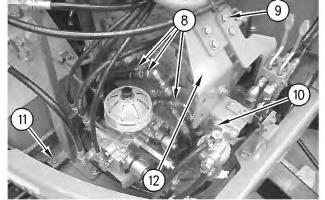
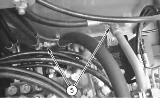
- Position the water separator and install bolts (10) .
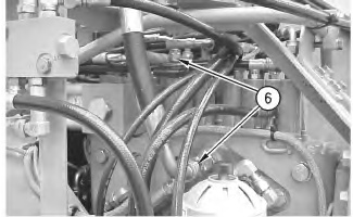
- Position the bracket and install bolts (9) .
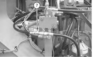
- Connect three hose assemblies (8) to the right side of the control valve.