Assembly Procedure
Note: Inspect all of the O-ring seals prior to assembly of the main control valve. Replace any O-ring seals which are worn or damaged with new O-ring seals.
|
|
| NOTICE |
|---|
|
Keep all parts clean from contaminants. Contaminants may cause rapid wear and shortened component life. |
|
|
|
Improper assembly of parts that are spring loaded can cause bodily injury. To prevent possible injury, follow the established assembly procedure and wear protective equipment. |
Attachment Control Valve (If Equipped)
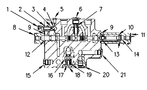
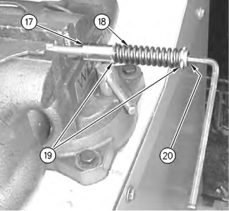
- Install seats (19), spring (18), and rod (20) on spool (17). Tighten rod (20) to a torque of 21 ± 2 N·m (15 ± 1 lb ft).
|
|
|
|
|
|
| Illustration 1 | g00878426 |
|
Two attachment control valves are illustrated. |
|
|
|
|
|
|
|
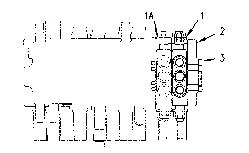
| Illustration 2 | g00878612 |
|
|
|
|
|
|
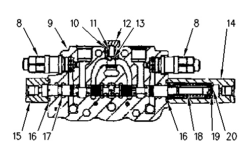
| Illustration 3 | g00878874 |
|
Improper assembly of parts that are spring loaded can cause bodily injury. To prevent possible injury, follow the established assembly procedure and wear protective equipment. |
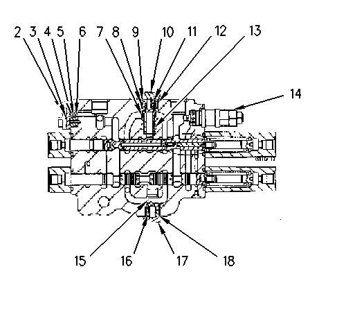
- Install the assembled components into housing (9) .
- Install O-ring seals (16) in covers (14) and (15). Secure covers (14) and (15) with the bolts. Tighten the bolts to a torque of 10.8 ± 1.0 N·m (95.59 ± 8.85 lb in).
- Install O-ring seal (10) on plug (12). Install spring (11), valve (13), plug (12), and O-ring seal (10). Tighten plug (12) to a torque of 93 ± 5 N·m (69 ± 4 lb ft).
|
Improper assembly of parts that are spring loaded can cause bodily injury. To prevent possible injury, follow the established assembly procedure and wear protective equipment. |
- Install two relief valves (8) in housing (9). Tighten the relief valves to a torque of 64 ± 5 N·m (47 ± 4 lb ft).
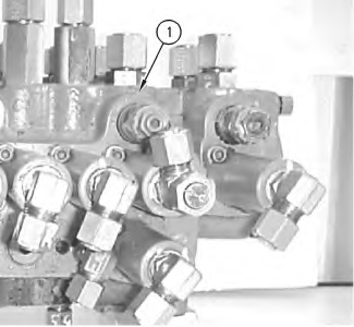
- Install attachment control valves (1) and (1A), and install cover (2). Secure the components with bolts (3). Tighten the bolts to a torque of 61 ± 4 N·m (45 ± 3 lb ft).
Main Control Valve
|
|
|
|
|
|
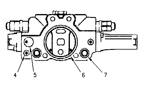
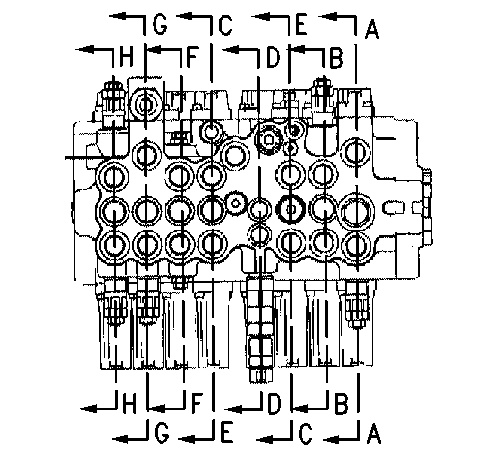
| Illustration 5 | g00878889 |
|
(A-A) Stick 1 Valve (B-B) Swing Valve (C-C) Travel Valve (D-D) Straight Travel Valve (E-E) Travel Valve (F-F) Option Valve (G-G) Boom 1 Valve (H-H) Bucket Valve |
|
Stick 1 Valve
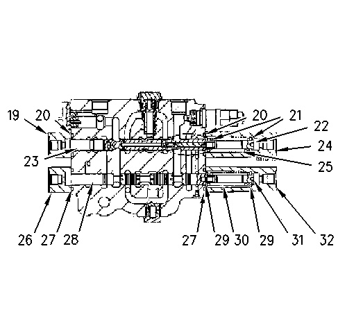
- Assemble seats (29) and spring (30) on spool (28). Install rod (31) and tighten rod (31) to a torque of 21 ± 2 N·m (15 ± 1 lb ft).
|
|
|
|
|
|
| Illustration 6 | g00878435 |
|
|
|
|
|
|
| Illustration 7 | g00885668 |
|
Improper assembly of parts that are spring loaded can cause bodily injury. To prevent possible injury, follow the established assembly procedure and wear protective equipment. |
- Install the assembled components in housing (1) .
- Install O-ring seals (27) in covers (26) and (32). Position covers (26) and (32) on the housing and secure the covers with the bolts. Tighten the bolts to a torque of 10.8 ± 1.0 N·m (95.59 ± 8.85 lb in).
- Assemble seats (21) and spring (25) on spool (23). Install rod (22) and tighten rod (22) to a torque of 21 ± 2 N·m (15 ± 1 lb ft).
|
Improper assembly of parts that are spring loaded can cause bodily injury. To prevent possible injury, follow the established assembly procedure and wear protective equipment. |
- Install the assembled components in housing (1) .
- Install O-ring seals (20) in covers (19) and (24). Position covers (19) and (24) on the housing and secure the covers with the bolts. Tighten the bolts to a torque of 10.8 ± 1.0 N·m (95.59 ± 8.85 lb in).
- Install O-ring seal (18) on plug (17). Install spring (16) and valve (15) .
|
|
|
|
|
|
| Illustration 8 | g00878939 |
|
Improper assembly of parts that are spring loaded can cause bodily injury. To prevent possible injury, follow the established assembly procedure and wear protective equipment. |
- Install plug (17) and seal (18). Tighten the plug to a torque of 93 ± 5 N·m (69 ± 4 lb ft).
- Install relief valve (14) in housing (1). Tighten the relief valve to a torque of 64 ± 5 N·m (47 ± 4 lb ft).
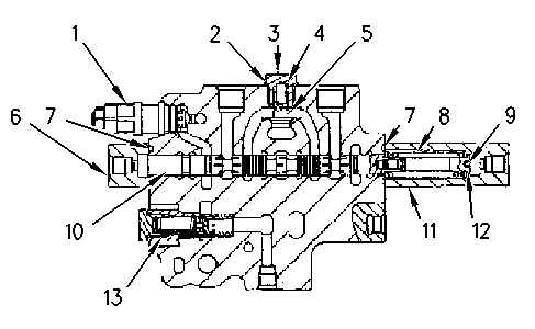
- Install O-ring seal (9) on plug (10) .
- Install valve (7 ) and spring (8). Install sleeve (13), valve (12), and spring (11) .
|
Improper assembly of parts that are spring loaded can cause bodily injury. To prevent possible injury, follow the established assembly procedure and wear protective equipment. |
- Install O-ring seal (9) and plug (10). Tighten plug (10) to a torque of 182 ± 15 N·m (134 ± 11 lb ft).
- Install O-ring seal (9) on plug (10) .
- Install ring (4), O-ring seal (5), and spacer (6) in the housing. Install O-ring seals (3). Install plate (2) and secure the plate with the bolts. Tighten the bolts to a torque of 10.8 ± 1.0 N·m (95.59 ± 8.85 lb in).
Swing Valve
- Assemble seats (12) and spring (8) on spool (10). Install rod (9) and tighten the rod to a torque of 21 ± 2 N·m (15 ± 1 lb ft).
|
|
|
|
|
|
| Illustration 9 | g00878927 |
|
Improper assembly of parts that are spring loaded can cause bodily injury. To prevent possible injury, follow the established assembly procedure and wear protective equipment. |
- Install the assembled components in the housing.
- Install O-ring seals (7) in covers (6) and (11). Position covers (6) and (7) on the housing and secure the covers with the bolts. Tighten the bolts to a torque of 10.8 ± 1.0 N·m (95.59 ± 8.85 lb in).
- Install O-ring seal (2) on plug (3) .
- Install spring (4) and valve (5).
|
Improper assembly of parts that are spring loaded can cause bodily injury. To prevent possible injury, follow the established assembly procedure and wear protective equipment. |
- Install plug (3) and O-ring seal (2). Tighten the plug to a torque of 93 ± 5 N·m (69 ± 4 lb ft).
- Install relief valve (1). Tighten relief valve (1) to a torque of 64 ± 5 N·m (47 ± 4 lb ft).
- Install relief valve (13). Tighten relief valve (13) to a torque of 54 ± 5 N·m (40 ± 4 lb ft).