Table 1
| Required Tools |
| Tool |
Part Number |
Part Description |
Qty |
| A |
1P-1861 |
Retaining Ring Pliers |
1 |
| B |
1P-0510 |
Driver Group |
1 |
| C |
– |
Pipe (1) |
1 |
| ( 1 ) |
The inside diameter of the pipe should be a minimum of 36 millimeters. The length of the pipe should be a minimum of 110 millimeters. |
Note: Regular maintenance and frequent inspections are routine precautions. Practice preventive maintenance before damage occurs. Preventive maintenance can help to avoid a failure. If a failure occurs, an accurate diagnosis of the cause can prevent a recurrence. Information is available to analyze the failures of the piston pump and of the motor. Refer to Special Publication, SEBD0641, “Analyzing Axial Piston Pump and Motor Failures.”.
Note: Cleanliness is an important factor. Before assembly, thoroughly clean all parts in cleaning fluid. Allow the parts to air dry. Do not use wiping cloths or rags to dry parts. Lint may be deposited on the parts which may cause trouble. Inspect all parts. If any parts are worn or damaged, use new parts for replacement. Dirt and other contaminants can damage the precision component. Perform assembly procedures on a clean work surface. Keep components covered and protected at all times. During the assembly of the main hydraulic pump, lubricate all of the parts with clean hydraulic oil. Do not mix components during the assembly process. Ensure that all components are assembled in original positions.
|
| NOTICE |
|
Failure to properly assemble parts or failure to follow established procedures can lead to damage of the parts and assembly.
To avoid damage to parts, always identify and mark the parts so that they can be installed in the same location. Ensure that gear surfaces align. Never force parts during assembly.
|
|
|
|
|
|
| Illustration 1 |
g00884353 |
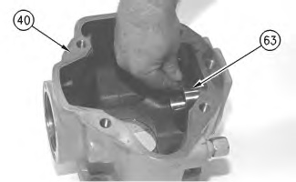
- Install bearing cup (63) in pump housing (40). Properly seat the bearing cup in the pump housing bore. If necessary, use a soft faced hammer to seat the bearing cup.
|
|
|
|
| Illustration 2 |
g00884351 |
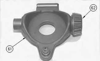
- Install bearing cone (62) on swashplate (61), as shown. Properly seat the bearing cone on the swashplate. If necessary, use a soft faced hammer to seat the bearing cone.
- Apply clean hydraulic oil on bearing cone (62) and on bearing cup (63) .
|
|
|
|
| Illustration 3 |
g00884347 |
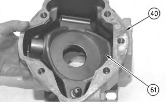
- Position swashplate (61) in pump housing (40) .
|
|
|
|
| Illustration 4 |
g00884340 |
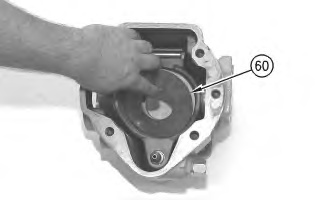
- Install plate (60) in the swashplate.
|
|
|
|
| Illustration 5 |
g00884604 |
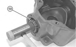
- Install bearing cone (59) on the swashplate, as shown. Properly seat the bearing cone on the swashplate. If necessary, use a soft faced hammer to seat the bearing cone.
|
|
|
|
| Illustration 6 |
g00884656 |
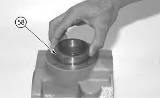
- Install bearing cup (58) in the pump housing, as shown. Properly seat the bearing cup in the pump housing. If necessary, use a soft faced hammer to seat the bearing cup.
|
|
|
|
| Illustration 7 |
g00884681 |
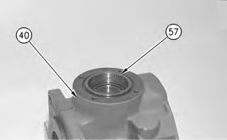
- Temporarily install collar (57) in pump housing (40), as shown.
- Use the following procedure to adjust the preload of the bearings on swashplate (61) .
Note: Collar (57) controls the amount of bearing preload.
|
|
|
|
| Illustration 8 |
g00884690 |
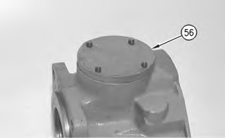
- Without the O-ring seal, position cover (56) on the pump housing.
- Use a feeler gauge to measure the space between the pump housing and cover (56) in three places. Calculate the average of the three gauge measurements. Record the average.
- The correct space is 0.070 to 0.120 mm (0.0028 to 0.0047 inch). If the space that is measured in Step 9.b is greater than 0.120 mm (0.0047 inch), machine collar (57) to the correct measurement. If the space that is measured in Step 9.b is smaller than 0.120 mm (0.0047 inch), install a new collar.
Note: Only one type of collar is available.
- Repeat Step 9.a through Step 9.c until the collar meets the required specifications.
|
|
|
|
| Illustration 9 |
g00883990 |
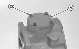
- Position the O-ring seal and cover (56) on the pump housing. Install socket head bolts (55). Tighten the socket head bolts to a torque of 32 ± 4 N·m (24 ± 3 lb ft).
|
|
|
|
| Illustration 10 |
g00883979 |
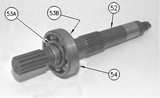
- Use Tooling (A) to install retaining ring (53B) on shaft (52) .
- Use Tooling (C) and a suitable press to install shaft (52) in bearing (54) .
- Properly seat the bearing against retaining ring (53B). Use Tooling (A) to install second retaining ring (53A) on the shaft.


