Disassembly Procedure
| Required Tools | |||
| Tool | Part Number | Part Description | Qty |
| A | 1P-1861 | Retaining Ring Pliers | 1 |
| B | 1P-0510 | Driver Group | 1 |
Start By:
- Remove the main hydraulic pump. Refer to Disassembly and Assembly, “Main Hydraulic Pump – Remove”.
Note: Cleanliness is an important factor. Before you begin the disassembly procedure, the exterior of the components should be thoroughly cleaned. This will help to prevent dirt from entering the internal mechanism. Precision components can be damaged by contaminants or by dirt. Perform disassembly procedures on a clean work surface. Keep components covered and protected at all times.
Note: After disassembly has been completed, check the condition of all the components. Refer to Guidelines For Reusable Parts, SEBF8032, “Piston Pumps and Motors”. During reconditioning, correct any conditions that might have caused the original failure. Information is available to analyze failures on the piston pumps and on the motor. Refer to Special Publication, SEBD0641, “Analyzing Axial Piston Pump and Motor Failures”.
|
|
| NOTICE |
|---|
|
Care must be taken to ensure that fluids are contained during performance of inspection, maintenance, testing, adjusting and repair of the product. Be prepared to collect the fluid with suitable containers before opening any compartment or disassembling any component containing fluids. Refer to Special Publication, NENG2500, “Caterpillar Tools and Shop Products Guide” for tools and supplies suitable to collect and contain fluids on Caterpillar products. Dispose of all fluids according to local regulations and mandates. |
|
|
|
|
| NOTICE |
|---|
|
Keep all parts clean from contaminants. Contaminants may cause rapid wear and shortened component life. |
|
|
|
Personal injury can result from being struck by parts propelled by a released spring force. Make sure to wear all necessary protective equipment. Follow the recommended procedure and use all recommended tooling to release the spring force. |
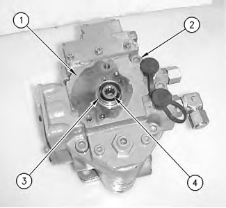
- Remove coupling (4). Remove bushing (3). Remove bolts (2) and remove cover (1) .
|
|
|
|
|
|
| Illustration 1 | g00881676 |
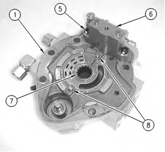
- Remove bearing (7) from cover (1). Remove pins (8). Remove bolts (5) and cylinder (6) .
|
|
|
|
|
|
| Illustration 2 | g00881935 |
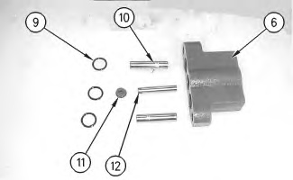
- Remove O-ring seals (9) from cylinder (6). Remove orifice (11). Remove piston (12). Remove two pistons (10) .
|
|
|
|
|
|
| Illustration 3 | g00882015 |
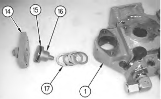
- Remove seat (16). Remove O-ring seal (15) from the seat. Remove shims (17) .
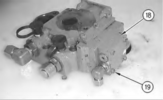
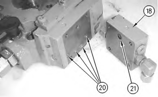
- Remove O-ring seal (21) from plate (18). If necessary, remove plugs (20) from the cover.
|
|
|
|
|
|
| Illustration 7 | g00882318 |
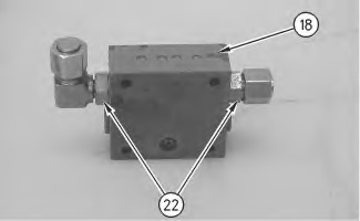
- Use the following Steps in order to disassemble plate (18) .
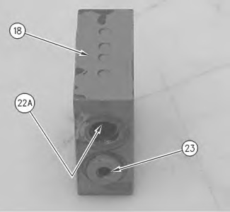
- Remove orifice (22A). Remove plug (23) from plate (18) .

Personal injury can result from parts and/or covers under spring pressure.
Spring force will be released when covers are removed.
Be prepared to hold spring loaded covers as the bolts are loosened.

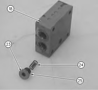
Illustration 9 g00882668 - Remove spring (24) from plate (18). Remove O-ring seal (25) from plug (23) .
Illustration 10 g00882671
