|
|
|
|
|
|
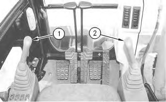
| Illustration 1 | g00871337 |
|
Inside cab (1) Pilot control valve (stick and swing) (2) Pilot control valve (boom and bucket) |
|
|
|
|
|
|
|
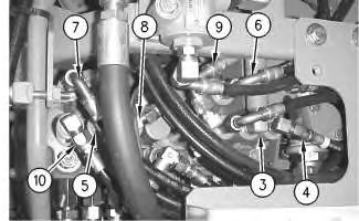
| Illustration 2 | g00871338 |
|
Main control valve compartment (top view) The storage box is removed for clarity. (3) Pilot line for boom I (BOOM LOWER) (4) Pilot line (BUCKET CLOSE) (5) Pilot line (SWING RIGHT) (6) Pilot line for boom II (BOOM RAISE) (7) Pilot line for stick II (STICK IN) (8) Pilot line for right travel (FORWARD) (9) Pilot line for left travel (FORWARD ) (10) Pilot line for stick I (STICK IN) |
|
Four valves are contained within each pilot control valve. Pilot control valve (1) controls STICK IN, STICK OUT, SWING RIGHT and SWING LEFT movements. Pilot control valve (2) controls BOOM RAISE, BOOM LOWER, BUCKET OPEN and BUCKET CLOSE movements.
Pilot control valve (1) and pilot control valve (2) send pilot pump oil to the main control valve through the following pilot lines:
- Pilot line (3) for boom I BOOM LOWER
- Pilot line (4) for BUCKET CLOSE
- Pilot line (5) for SWING RIGHT
- Pilot line (6) for boom II BOOM RAISE
- Pilot line (7) for stick II STICK IN
- Pilot line (10) for stick I STICK IN
Pilot oil from the pilot control valves flows through pilot lines to the ports on the bottom of the main control valve in order to perform the opposite operation.
Pilot Control Valve Operation
|
|
|
|
|
|
| Illustration 3 | g00755423 |
|
Pilot control valve (implement and swing) (1) Pilot control lever (2) Rod (3) Return passage (4) Passage (5) Spool (6) Plate (7) Rod (10) Seat (11) Metering spring (12) Spring (13) Return chamber (14) Return passage (15) Passage (16) Spool (17) Port (18) Passage (19) Port (20) Port (21) Port |
|
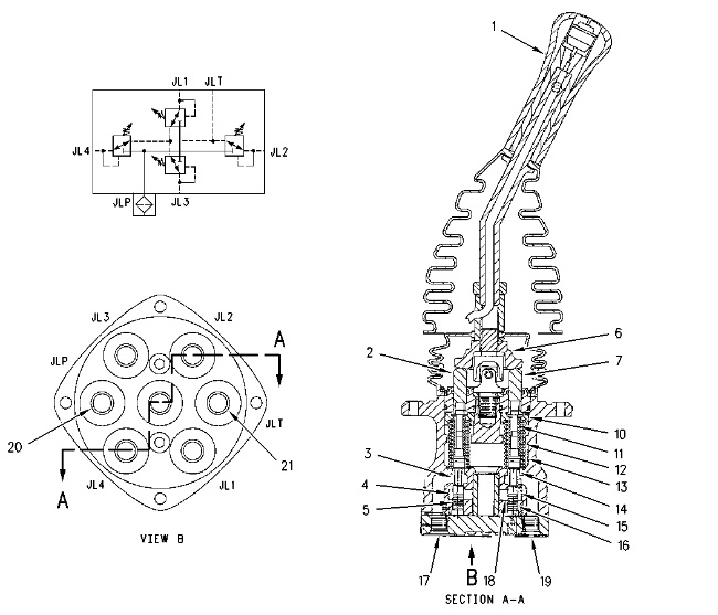
When the pilot control lever (1) is moved to the right, plate (6) tilts to the right. Plate (6) pushes down on rod (7) and seat (10). Seat (14) pushes against the force of metering spring (11) and spring (12). The force of metering spring (11) shifts spool (16) in a downward direction. Passage (15) opens. The pilot oil flows through port (20), passage (18), passage (15) and port (19) to the main control valve. The oil pressure shifts the stem of the main control valve. This enables the implement operation or swing operation.
The return pilot oil at the opposite end of the spool in the main control valve returns to the pilot control valve through port (17). Since rod (2) is not pushed down by plate (6), return passage (3) is open and passage (4) is closed. The return pilot oil flows through return passage (3), return chamber (13) and port (21) to the hydraulic tank.
The force of metering spring (11) varies with the position of the joystick. Since spool (16) is moved by the force of metering spring (11), the pilot oil pressure that flows through passage (15) to the main control valve directly corresponds with the position of the joystick. Spool modulation in the main control valve directly corresponds with the amount of movement of the joystick.
When the joystick is moved slightly from the NEUTRAL position, metering spring (11) moves spool (16) slightly. Low pilot oil pressure is sent to the spool of the main control valve. The main control valve spool shifts a slight amount. The volume of oil delivery to the cylinders and/or motors is small. The speed of the cylinders and/or motors is slow. As the joystick is moved farther from the NEUTRAL position, the force of metering spring (11) on spool (16) increases. The pilot oil pressure that is sent to the main control valve increases. The spool in the main control valve shifts farther and the speed of the cylinders and/or motors increases. Thus, cylinder speed and motor speed is controlled by the amount of movement and the position of the joystick. Fine control of the cylinders and/or motors is accomplished since the pilot oil pressure that is sent to the main control valve is decreased.
When the joystick is released, the joystick will return to the NEUTRAL position due to the force of spring (12) .