Line Relief Valves and Makeup Valves
The line relief valve and the makeup valve are located between the cylinder and the control valve. The control valve is in the NEUTRAL position. Outside force acts against a cylinder. The pressure increases in the cylinder and the circuit to the control valve. All of the line relief valves operate at a pressure of 31000 kPa (4500 psi). The line relief valve also operates as a makeup valve.
The control valve is in the NEUTRAL position. When an outside force acts on the implement cylinder, the cylinder piston will try to move. A vacuum condition will occur in the cylinder. The makeup valve sends a portion of the return oil to the cylinder, which removes the vacuum condition.
|
|
|
|
|
|
| Illustration 1 | g00418158 |
|
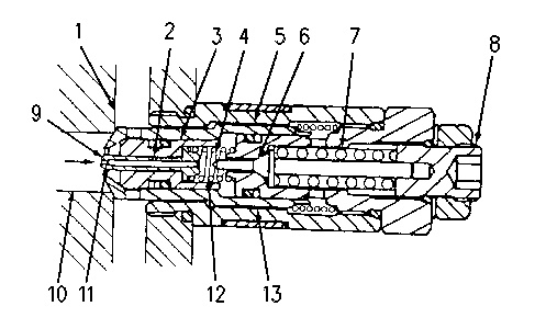
Line relief valve (closed position) (1) Return passage (2) Passage (3) Valve (4) Spring (5) Valve (6) Valve (7) Spring (8) Adjusting screw (9) Piston (10) Cylinder passage (11) Orifice (12) Spring chamber (13) Passage |
|
High pressure oil from cylinder passage (10) enters the line relief valve. The oil flows through orifice (11), through the opening of piston (9) and into spring chamber (12). Spring chamber (12) has more surface area than cylinder passage (10). The oil pressure in spring chamber (12) causes valve (3) and valve (5) to shift all the way to the left. Valve (3) and valve (5) are held in this position. With the force of spring (7) beyond the oil pressure from cylinder passage (10), valve (6) remains closed. Oil flow from passage (10) is blocked by spring chamber (12) and oil cannot flow to return passage (1).
|
|
|
|
|
|
| Illustration 2 | g00418279 |
|
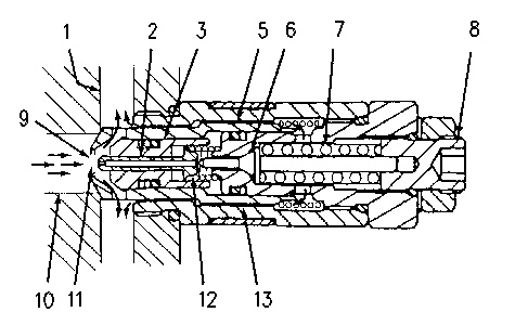
Line relief valve (open position) (1) Return passage (2) Passage (3) Valve (5) Valve (6) Valve (7) Spring (8) Adjusting screw (9) Piston (10) Cylinder passage (11) Orifice (12) Spring chamber (13) Passage |
|
The oil pressure in passage (10) increases to the relief valve setting. Valve (6) shifts to the right (open position). This allows oil from passage (10) to flow through passage (13) to return passage (1) .
Because oil from passage (10) is restricted at orifice (11), oil pressure in spring chamber (12) becomes lower than the oil pressure in passage (10). Piston (9) shifts to the right and seats on valve (6). Oil flow through orifice (11) goes through passage (2), around piston (9) and into spring chamber (12). Oil pressure in passage (10) is higher than oil pressure in spring chamber (12). The oil pressure from passage (10) shifts valve (3) to the right (open position). This allows part of pressure oil in passage (10) to flow to return passage (1). The oil pressure in passage (10) is now kept at the line relief valve pressure setting.
Turn adjusting screw (8) in order to adjust the line relief valve pressure setting.
Makeup Valve Operation
|
|
|
|
|
|
| Illustration 3 | g00418350 |
|
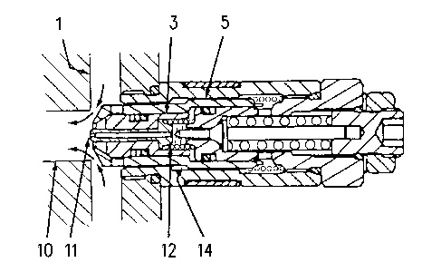
Line relief valve (makeup valve in operation) (1) Return passage (3) Valve (5) Valve (10) Cylinder passage (11) Orifice (12) Spring chamber (14) Shoulder |
|
A vacuum condition can occur in the following manner.
- Oil is depleted through the operation of the line relief valve for the rod end of a cylinder. The oil must be replaced in the head end in order to prevent a vacuum condition.
- Oil is depleted through the operation of the line relief valve for the head end of a cylinder. The oil must be replaced in the rod end in order to prevent a vacuum condition.
Because cylinder passage (10) is connected to spring chamber (12) through orifice (11), a vacuum condition can occur in cylinder passage (10) and in spring chamber (12). The oil pressure from return passage (1) acts on shoulder (14) of valve (5). Shoulder (14) receives negative control pressure from spring chamber (12). Valve (5) shifts to the right. The oil flows from return passage (1) into cylinder passage (10) as makeup oil. This removes the vacuum condition in passage (10) .


