| Required Tools | ||
|---|---|---|
| Part Number | Description | Qty |
| 8T-0861 | Pressure Gauge ( 60000 kPa (8700 psi)) |
1 |
| FT-2547 | Track Block Assembly | 1 |
| 6V-9507 | Face Seal Plug | 1 |
| 6V-9829 | Cap As | 1 |
| 4J-5477 | O-Ring Seal | 2 |
Note: In order to adjust the main relief valve, always adjust the travel operation of the main relief valve before adjustments are made to the implement operation of the main relief valve. An adjustment to the travel operation of the main relief valve will change the pressure setting of the implement operation of the main relief valve.
Travel Operation
- Position the machine on level ground.
- Stop the engine.
- Release the pressure in the hydraulic system. Refer to Testing And Adjusting, “Hydraulic System Pressure – Release”.
- Attach a 60000 kPa (8700 psi) pressure gauge to pressure tap (2) .
|
|
|
|
|
|
| Illustration 1 | g00858167 |
|
Pump compartment (1) Pressure tap (right pump delivery pressure) (2) Pressure tap (left pump delivery pressure) |
|

- Disconnect hose (4) from main relief valve (8) .
|
|
|
|
|
|
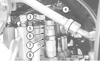
| Illustration 2 | g00858174 |
|
Top of main control valve (3) Adjustment screw (4) Hose (5) Locknut (6) Adjustment screw (7) Locknut (8) Main relief valve |
|
- Install 4J-5477 O-Ring Seal and 6V-9507 Face Seal Plug in the end of hose (4) .
- Install 6V-9829 Cap and 4J-5477 O-Ring Seal on the opening of main relief valve (8) .
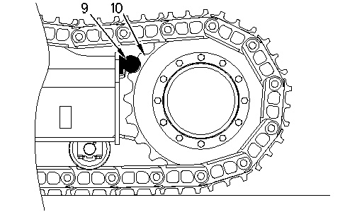
- Place track block assembly (9) in sprocket (10) in order to block forward left travel.
|
|
|
|
|
|
| Illustration 3 | g00728723 |
|
(9) FT-2547 Track Block Assembly (10) Sprocket |
|
- Start the engine.
- Place the machine controls at the following settings: engine speed dial “10” and Low idle switch OFF. Refer to Testing and Adjusting, “Engine Performance – Test” for engine rpm settings.
- Place the hydraulic activation control lever in the UNLOCKED position.
- Increase the hydraulic oil temperature to 55° ± 5°C (131° ± 9°F).
- Loosen locknut (5) and turn adjustment screw (3) until the adjustment screw contacts the bottom. Do not overtighten adjustment screw (3) .. Tighten locknut (5) .
- Slowly move the left travel control lever to full FORWARD position and check the pressure gauge reading at pressure tap (2). The pressure setting should be 31500 ± 500 kPa (4550 ± 75 psi).
- Return the left travel control lever to the NEUTRAL position.
- In order to adjust the travel operation of the main relief valve, loosen locknut (7) and turn adjustment screw (6) until the pressure gauge reading at pressure tap (2) is 31500 ± 500 kPa (4550 ± 75 psi).
Note: Turn adjustment screw (6) clockwise in order to increase the pressure. Turn adjustment screw (6) counterclockwise in order to decrease the pressure.
Note: Always make final pressure adjustments on pressure rise.
- Tighten locknut (7) to a torque of 80 ± 5 N·m (60 ± 5 lb ft).
Implement Operation
- Position the machine on level ground.
- Stop the engine.
- Release the pressure in the hydraulic system. Refer to Testing And Adjusting, “Hydraulic System Pressure – Release”.
- Attach a 60000 kPa (8700 psi) pressure gauge to pressure tap (2) .
|
|
|
|
|
|
| Illustration 4 | g00858167 |
|
Pump compartment (1) Pressure tap (right pump delivery pressure) (2) Pressure tap (left pump delivery pressure) |
|
- Disconnect hose (4) from main relief valve (8) .
|
|
|
|
|
|
| Illustration 5 | g00858174 |
|
Top of main control valve (3) Adjustment screw (4) Hose (5) Locknut (6) Adjustment screw (7) Locknut (8) Main relief valve |
|
- Install 4J-5477 O-Ring Seal and 6V-9507 Face Seal Plug in the end of hose (4) .
- Install 6V-9829 Cap and 4J-5477 O-Ring Seal on the opening of main relief valve (8) .
- Start the engine.
- Place the machine controls at the following settings: engine speed dial “10” and Low idle switch OFF. Refer to Testing and Adjusting, “Engine Performance – Test” for engine rpm settings.
- Place the hydraulic activation control lever in the UNLOCKED position.
- Increase the hydraulic oil temperature to 55° ± 5°C (131° ± 9°F).
- Slowly move the joystick for the bucket to the BUCKET CLOSE position (full extension of the bucket cylinder rod). Check the pressure gauge reading at pressure tap (2). The pressure setting should be 27500 ± 500 kPa (4000 ± 75 psi).
- Return the joystick for the bucket to the NEUTRAL position.
- In order to adjust the implement operation of the main control valve, loosen locknut (5) and turn adjustment screw (3) until the pressure gauge reading at pressure tap (2) is 27500 ± 500 kPa (4000 ± 75 psi).
Note: Turn adjustment screw (3) clockwise in order to increase the pressure. Turn adjustment screw (3) counterclockwise in order to decrease the pressure.
Note: Always make final pressure adjustments on pressure rise.
- Tighten locknut (5) to a torque of 65 ± 5 N·m (45 ± 5 lb ft).
- Stop the engine.
- Release the pressure in the hydraulic system. Refer to Testing And Adjusting, “Hydraulic System Pressure – Release”.
- Remove the plug from hose (4) .
- Remove the cap from main relief valve (8) .
- Connect hose (4) to main relief valve (8) .
Temporary Setting of the Main Relief Valve
- The main relief valve pressure setting should be 27500 ± 500 kPa (4000 ± 75 psi). If the main relief valve is not within the specification, adjust the main relief valve pressure setting to the correct pressure specification before performing Step 2. Refer to Testing and Adjusting, “Relief Valve (Main) – Test and Adjust”.
- Disconnect hose (4) from main relief valve (8) .
|
|
|
|
|
|
| Illustration 6 | g00858174 |
|
Top of main control valve (3) Adjustment screw (4) Hose (5) Locknut (6) Adjustment screw (7) Locknut (8) Main relief valve |
|
- Install 6V-9507 Face Seal Plug and 4J-5477 O-Ring Seal in the open end of hose (4) .
- Install 6V-9829 Cap and 4J-5477 O-Ring Seal on the opening of main relief valve (8) .
- Loosen locknut (7) and turn adjustment screw (6) clockwise for one quarter turn.
Note: Turn adjustment screw (6) clockwise in order to increase the pressure. Turn adjustment screw (6) counterclockwise in order to decrease the pressure.
Note: Always make final pressure adjustments on pressure rise.
- The pressure gauge reading at pressure tap (1) or pressure tap (2) should be approximately 33300 kPa (4850 psi).
- Tighten locknut (7) to the specified torque.