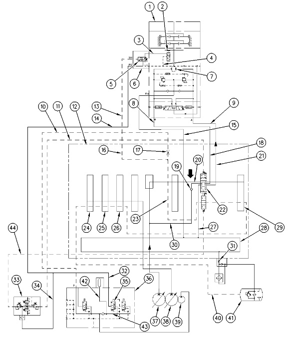
Hydraulic Schematic For Swing Right
|
|
|
|
|
|
| Illustration 1 | g00756443 |
|
Hydraulic schematic for swing right (1) Swing motor (2) Swing parking brake (3) Passage (4) Passage (5) Spool (6) Control valve for swing parking brake (7) Motor rotary group (8) Line (9) Line (10) Pilot line (11) Pilot line (12) Main control valve (13) Line (14) Line (15) Line (16) Passage (17) Orifice (18) Passage (19) Load check valve (20) Passage (21) Passage (22) Swing control valve (23) Passage (24) Bucket control valve (25) Boom I control valve (26) Attachment control valve (27) Passage (28) Return passage (29) Stick I control valve (30) Parallel feeder passage (31) Slow return check valve (32) Line (33) Pilot control valve (swing and stick) (34) Line (35) Hydraulic activation control valve (36) Pilot oil manifold (37) Right pump (38) Left pump (39) Pilot pump (40) Drain line (41) Hydraulic oil tank (42) Passage (43) Passage (44) Pilot line |
|
Swing Control
Introduction
Swing motor (1) is driven by pressure oil from right pump (37). When the swing control lever is moved, swing parking brake (2) is released. The motor rotary group (7) of the swing motor (1) starts to rotate.
The swing drive reduces the motor speed through two stages of gear reduction before rotating the upper structure.
Swing Right Operation
|
|
|
|
|
|
| Illustration 2 | g00870408 |
|
Swing motor (8) Line (9) Line |
|
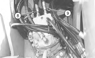
When the control lever is moved to the SWING RIGHT position, pilot oil from pilot control valve (33) goes through pilot line (11) to swing control valve (22). The stem in swing control valve (22) is shifted downward by the pilot oil in order to connect passage (20) to passage (21) .
Right pump oil is supplied to passage (20) through parallel feeder passage (30) and load check valve (19). From passage (20), the oil goes through passage (21), and line (9) to the motor rotary group (7). At this time, the swing parking brake is released.
Return oil from the motor rotary group (7) goes through line (8) to swing control valve (22). The return oil then goes through return passage (27) to return line (28). The motor rotary group (7) of the swing motor rotates the upper structure for a RIGHT SWING operation.
Swing Parking Brake Operation
ON Position
|
|
|
|
|
|
| Illustration 3 | g00870416 |
|
Swing motor (control valve for swing parking brake) (6) Control valve for swing parking brake (13) Pilot line (14) Line |
|
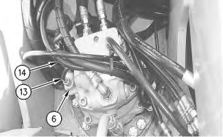
Pilot oil from pilot pump (39) enters pilot manifold (36). This oil separates into two paths. One pilot oil (43) goes through hydraulic activation control valve (35), line (32), and line (14) to the control valve for swing parking brake (6). Pilot oil (42) flows through line (10), orifice (17), and main control valve (12). The pilot oil then separates into two paths.
Pilot oil (23) goes through the following control valves and returns to the hydraulic tank (41) : swing control valve (22), stick I control valve (29), attachment control valve (26), boom I control valve (25) and bucket control valve (24). Pilot oil (16) flows through line (13) to control valve (6) for the swing parking brake. Oil flow in line (10) is restricted by orifice (17). The restriction causes a decrease in oil pressure in pilot line (23) and pilot line (16) .
The oil pressure in passage (16) cannot shift spool (5) in the control valve for swing parking brake (6). Passage (3) is open through line (4) to the drain line. Spring force applies the parking brake and the parking brake remains in the ON position.
OFF Position
The activation of any controls except travel will block pilot passage (23). This causes pilot oil pressure in passage (23) to increase. The pilot oil pressure in passage (16) and pilot line (13) also increases. The pressure in pilot line (13) causes spool (5) to shift. This allows the pilot oil from line (14) to flow to passage (3). The pilot oil pressure overcomes the spring force of the swing brake. This releases the swing parking brake (2) .
Activation of the travel control valve leaves pilot passage (23) open. Spool (5) does not shift and parking brake (2) remains engaged.
Because pilot passage (23) is blocked prior to the opening of swing control valve (22), the swing motor operates only after swing parking brake (2) is released by the pilot pressure from line (14) .
When swing and implement controls are in the NEUTRAL position, pilot passage (23) is open to drain line (40). This causes the pilot oil pressure in pilot passage (16) and pilot line (13) to decrease. Spring force returns spool (5) to the neutral position when the pilot oil pressure decreases. As a result, no pilot oil flows from line (14) to swing parking brake (2). The oil in swing parking brake (2) flows through passage (3) and line (4) to drain line. Swing parking brake (2) starts to activate as the pilot oil pressure decreases. The oil flow from passage (3) is restricted by a orifice within spool (5). A gradual application of swing parking brake (2) is the result. Swing parking brake (2) remains in the OFF position until the swing motor comes to a stop.
Note: For more information about the swing parking brake, refer to Systems Operation, “Pilot Valve (Swing Parking Brake)”.
Swing Left Operation
For a swing left operation, pilot oil is supplied through pilot line (44) to swing control valve (22). The pilot oil causes the stem in swing control valve (22) to shift in an upward direction. The right pump oil in parallel feeder passage (30) goes through swing control valve (22), passage (18) and passage (8). Right pump oil then enters the motor rotary group (7) of the swing motor. For a swing left operation, the supply ports and the return ports are the reverse of a swing right operation. This causes the upper structure to swing to the left.