Disassembly Procedure
| Required Tools | |||
| Tool | Part Number | Part Description | Qty |
| A | 1U-7506 | Transmission Adapter Kit | 1 |
| 8T-4244 | Nut (M12 by 1.75 inch) | 6 | |
| 8T-4223 | Hard Washer | 6 | |
| – | Threaded Rod (M12 by 1.75 by 6 inch) | 2 | |
| B | 8T-0296 | Bolt | 2 |
| 5P-8246 | Hard Washer | 2 | |
| 8T-3282 | Hard Washer | 2 | |
| C | 8H-0663 | Bearing Puller Gp | 1 |
| D | 1P-1861 | Retaining Ring Pliers | 1 |
Start By:
- Remove the swing motor. Refer to Disassembly and Assembly, “Swing Motor -Remove”.
Note: Cleanliness is an important factor. Before you begin the disassembly procedure, the exterior of the components should be thoroughly cleaned. This will help to prevent dirt from entering the internal mechanism. Precision components can be damaged by contaminants or by dirt. Perform disassembly procedures on a clean work surface. Keep components covered and protected at all times.
|
|
| NOTICE |
|---|
|
Care must be taken to ensure that fluids are contained during performance of inspection, maintenance, testing, adjusting and repair of the product. Be prepared to collect the fluid with suitable containers before opening any compartment or disassembling any component containing fluids. Refer to Special Publication, NENG2500, “Caterpillar Tools and Shop Products Guide” for tools and supplies suitable to collect and contain fluids on Caterpillar products. Dispose of all fluids according to local regulations and mandates. |
|
|
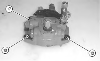
- Place swing motor (3) on appropriate blocking. The weight of the swing motor is approximately 37 kg (80 lb).
|
|
|
|
|
|
| Illustration 1 | g00874546 |
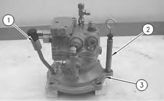
- Remove pipe assembly (1) and oil level gauge (2) .
Note: Note the orientation of pipe assembly (1) for installation purposes.
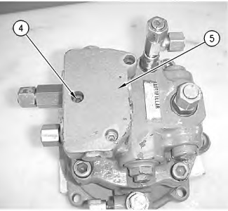
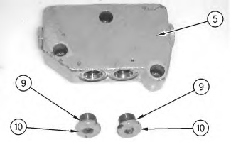
- Remove plugs (10) from the other side of makeup valve (5). Remove O-ring seals (9) .
|
|
|
|
|
|
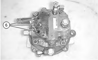
| Illustration 6 | g00874713 |
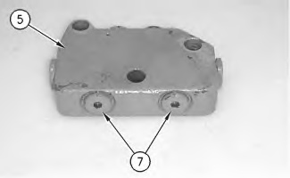
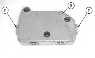
- Remove plugs (11) from makeup valve (5) .
|
Personal injury can result from parts and/or covers under spring pressure. Spring force will be released when covers are removed. Be prepared to hold spring loaded covers as the bolts are loosened. |
|
|
|
|
|
|
| Illustration 7 | g00874716 |
|
|
|
|
|
|
| Illustration 8 | g00874779 |
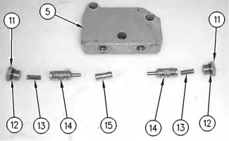
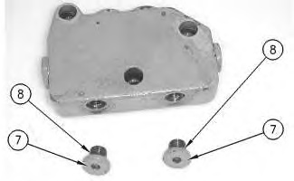
- Remove O-ring seals (12) from plugs (11). Remove springs (13), valves (14), and spool (15) from makeup valve (5) .