Note: The engine speed and/or the machine configuration that is used during this test can affect the results of this test. Refer to Testing and Adjusting, “Engine Performance – Test” for the engine speed that was used for this test. Refer to Testing and Adjusting, “Operational Checks” for the machine configurations that were used for this test.
Note: The relief valve pressure settings must be set to the relief valve pressure specification before performing this operational check. Refer to Testing and Adjusting, “Specifications”.
| Required Tools | ||
|---|---|---|
| Part Number | Description | Qty |
| 5P-3277 | Measuring Tape | 1 |
| Stopwatch | 1 | |
|
|
|
|
|
|
| Illustration 1 | g00298078 |
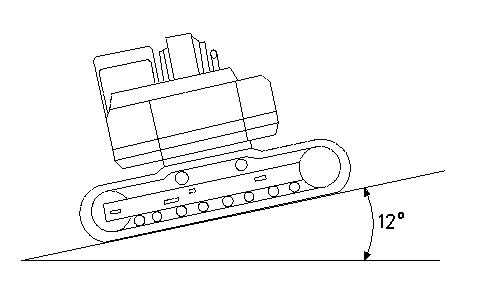
- Complete the following steps in order to measure the swing speed on a slope.
- Start the engine.
- Place the machine controls at the following settings: Engine speed dial “10” and Low idle switch OFF.
- Place the hydraulic activation control lever in the UNLOCKED position.
- Increase the hydraulic oil temperature to 55° ± 5°C (131° ± 9°F).
- The bucket should be empty.
- Position the machine on a slope of 12 degrees. Refer to Illustration 1.
- Position the implements at maximum reach and close the bucket. Position the bucket above the ground so that the bucket will not come in contact with any obstacles.
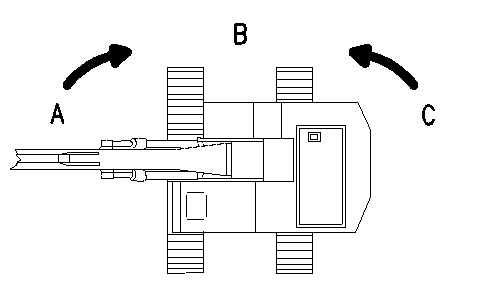
- Position the upper structure at position (A). The upper structure should be at a 90 degree angle to the lower structure. Refer to Illustration 2.
Illustration 2 g00298079 - Measure the time that is required to swing the upper structure from position (A) to position (B) .
- Position the upper structure at position (C). The upper structure should be at a 90 degree angle to the lower structure.
- Measure the time that is required to swing the upper structure from position (C) to position (B).
Table 2 Swing Time (seconds) Item New Rebuild Service Limit Right Swing 3.4 or less 3.9 or less 4.4 or less Left Swing
- Complete the following steps in order to measure the swing drift on a slope.
- Position the upper structure at position (A). The upper structure should be at a 90 degree angle to the lower structure. Refer to Illustration 3.
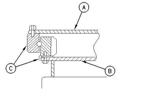
Illustration 3 g00298079 - To indicate the relationship of the two positions, put a mark (C) on the inner race and the outer race of the swing bearing. Refer to Illustration 4.
Illustration 4 g00293972 (A) Upper frame
(B) Undercarriage frame
(C) Marking
- Stop the engine.
- Leave the machine in this position for three minutes. Measure the swing drift on the circumference of the swing bearing.
- Start the engine.
- Position the upper structure at position (C). The upper structure should be at a 90 degree angle to the lower structure. Refer to Illustration 3.
- Repeat Steps 2.b through 2.d.
| Swing Drift mm (inch) | |||
|---|---|---|---|
| Item | New | Rebuild | Service Limit |
| Right Swing | 0 | 0 | 0 |
| Left Swing | |||