Note: When the procedure for the Travel Test On Level Ground cannot be performed, this test may be used as a substitute.
Note: The engine speed and/or the machine configuration that is used during this test can affect the results of this test. Refer to Testing and Adjusting, “Engine Performance – Test” for the engine speed that was used for this test. Refer to Testing and Adjusting, “Operational Checks” for the machine configurations that were used for this test.
Note: The relief valve pressure settings must be set to the relief valve pressure specification before performing this operational check. Refer to Testing and Adjusting, “Specifications”.
| Required Tools | ||
|---|---|---|
| Part Number | Description | Qty |
| Stopwatch | 1 | |
|
|
|
|
|
|
| Illustration 1 | g00297292 |
- Start the engine.
- Position the machine on level ground.
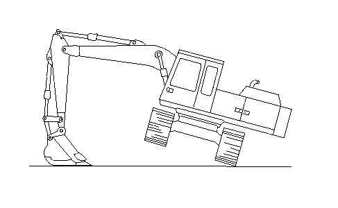
- Raise a track off the ground. Refer to Illustration 1.
- Put a mark on a shoe of the raised track.
- Place the machine controls at the following settings: Engine speed dial “10” and Low idle switch OFF.
- Place the travel speed control switch in HIGH position.
- Place the hydraulic activation control lever in the UNLOCKED position.
- Increase the hydraulic oil temperature to 55° ± 5°C (131° ± 9°F).
- Move the travel lever of the raised track to full travel position.
- Measure the time that is required for the raised track to make three complete revolutions. Measure the time that is required in each direction.
- Place the travel speed control switch in the LOW position and repeat Steps 9 through 10.
| Time For Three Revolutions (time in seconds) | ||||
|---|---|---|---|---|
| Travel Speed | New | Rebuild | Service Limit | |
| HIGH | Forward | 13.5 or less | 15.5 or less | 17.6 or less |
| Reverse | ||||
| LOW | Forward | 20.4 or less | 23.5 or less | 26.5 or less |
| Reverse | ||||
