|
|
|
|
|
|
| Illustration 1 | g00686271 |
|
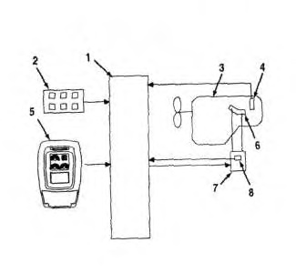
Diagram of Automatic Engine Control (AESC) for 312C through 322C (1) Engine and pump controller (2) Switch panel (3) Engine (4) Speed sensor (5) Monitor (6) Governor lever (7) Governor actuator (8) Feedback sensor |
|
|
|
|
|
|
|
| Illustration 2 | g00822672 |
|
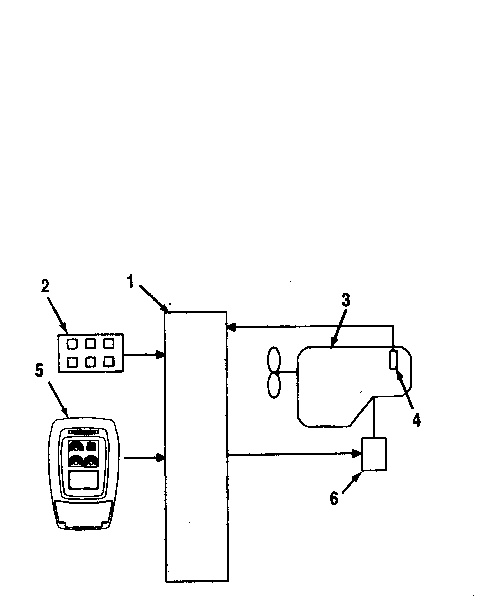
Diagram of the Automatic Engine Control (AESC) for 325C and 330C (1) Engine and pump controller (2) Switch panel (3) Engine (4) Speed sensor (5) Monitor (6) Electronic control module |
|
|
|
|
|
|
|
| Illustration 3 | g01057327 |
|
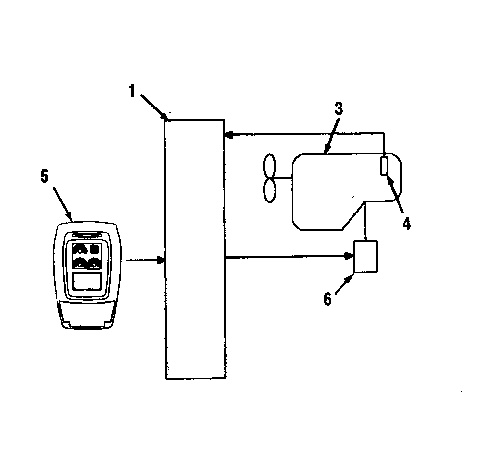
Diagram of the Automatic Engine Control (AESC) for 325C and 330C (1) Engine and pump controller (3) Engine (4) Speed sensor (5) Monitor (6) Electronic control module |
|
The AEC will lower the engine speed if no load on the machine continues for approximately three seconds or a light load on the machine continues for ten seconds when the engine speed dial is set in a position of 5 to 10. This process is designed to reduce the noise and fuel consumption. The AEC has settings in two stages. The AEC can be set by the switch on the right console. The indicator of the switch will illuminate during the second setting of the AEC. The second setting of the AEC is available immediately after the engine start switch is turned to the ON position. The AEC can be set in the first stage and the second stage by alternately pressing the switch.
First Setting Of The AEC
The first setting of the AEC will lower the speed of the setting of the engine speed dial by approximately 100 rpm in the “no load” or the “light load” condition.
Second Setting Of The AEC
The second setting of the AEC will reduce the engine speed to approximately 1300 rpm in the “no load” condition. The AEC will not function if the backup switch (MAN) is being operated.


