|
|
|
|
|
|
| Illustration 1 | g02529816 |
|
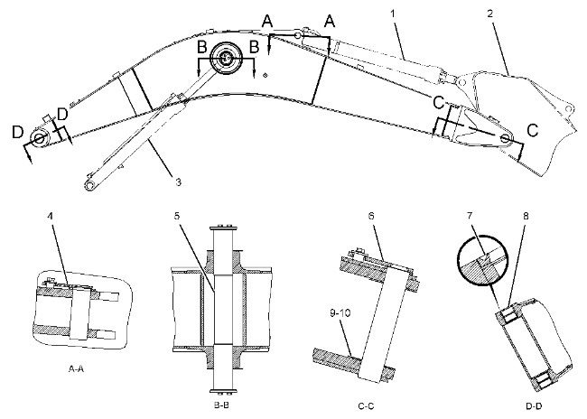
(1) Stick cylinder group (2) Stick group (3) Boom cylinder group |
|
| Specification for 236-8378 Boom, 236-8382 Boom, 282-4557 Boom, 290-9204 Boom, 290-9236 Boom, 294-1501 Boom, 324-1090 Boom, and 324-1093 Boom | |||
| Item | Qty | Part | Specification Description |
| All bores must be free of paint. Use 5P-0960 Grease Cartridge in order to coat all bores for the pins, the stick, the upper frame, and the cylinder pin bores. | |||
| 4 | 1 | 113-2963 Pin As | Pin diameter is 89.850 ± 0.025 mm (3.5374 ± 0.0010 inch). |
| 5 | 1 | 192-8321 Pin | Pin diameter is 109.850 ± 0.040 mm (4.3248 ± 0.0016 inch). |
| 6 | 1 | 251-2547 Pin As | Pin diameter is 119.850 ± 0.040 mm (4.7185 ± 0.0016 inch). |
| 7 | 2 | 166-1498 Lip Type Seal | Lubricate the sealing lip of the lip type seals lightly with the lubricant that is being sealed. Install the dust seal so that the lip faces outside, as shown. Install the lip type seals so that the lip type seals do not extend beyond the face of the boss. |
| 8 | 2 | Install the following bushings in the bore so that the part number of each bushing is facing outward. Bushing is one of the following part numbers: |
|
| 228-5621 Bushing | Inside diameter is 120.320 ± 0.040 mm (4.7370 ± 0.0016 inch). Installation depth is 9.5 ± 0.8 mm (0.37 ± 0.03 inch). |
||
| 236-8561 Bushing | Inside diameter is 120.200 ± 0.020 mm (4.7323 ± 0.0008 inch). Installation depth is 9.5 ± 0.8 mm (0.37 ± 0.03 inch). |
||
| Use the following shims as required in order to adjust the following maximum lateral clearance. The steel shim should be located at the boom side: Lateral clearance for Gosselies facility 1.0 mm (0.04 inch) .Lateral clearance except for Gosselies facility 1.6 mm (0.06 inch). |
|||
| 9 | 1 | 147-3957 Shim | Thickness is 0.50 mm (0.020 inch). |
| 10 | 1 | 093-0074 Shim | Thickness is 1.0 mm (0.04 inch). |
