|
|
|
|
|
|
| Illustration 1 | g00683978 |
|
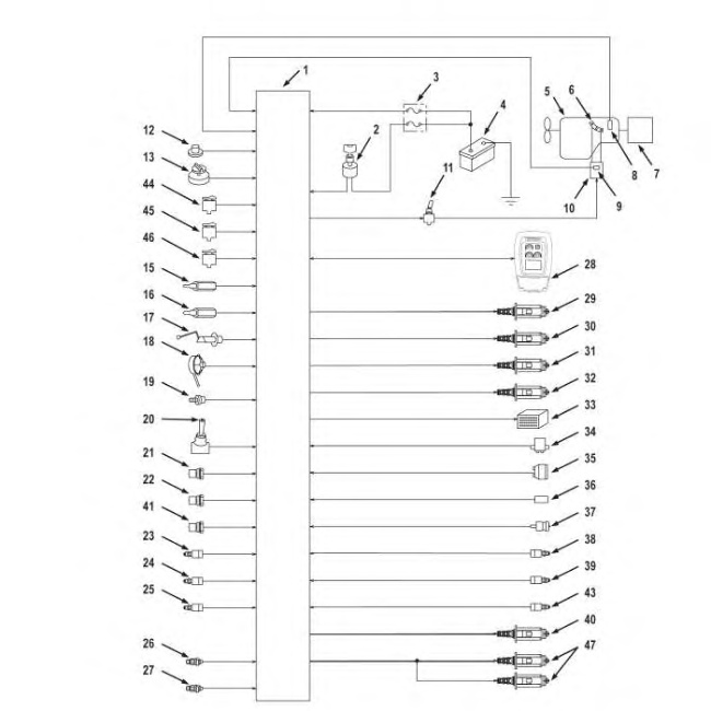
Block Diagram Of Inputs And Outputs Of The 312C, 315C, 318C, 319C, 320C, and 322C Controller (1) Engine and pump controller (2) Fuse Box (3) Engine (4) Governor lever (5) Hydraulic Pump (6) Battery (7) Start switch (8) Speed sensor (9) Backup switch (10) Governor actuator (11) Feedback sensor (12) Monitor (13) Action alarm (14) Engine speed dial (15) Switch panel (16) Engine coolant temperature sensor (17) Hydraulic oil temperature sensor (18) Fuel level sensor (19) Alternator (20) Engine oil pressure switch (21) One touch low idle switch (22) Engine oil level switch (23) Hydraulic oil level switch (24) Water separator level switch (25) Swing pressure switch for the implement (26) Travel pressure switch (left) (27) Travel pressure switch (right) (28) Pressure switch for the straight travel pedal (29) Pump pressure sensor (drive) (30) Pump pressure sensor (idle) (31) Proportional Reducing Valve (32) Solenoid for straight travel (33) Solenoid for travel speed (34) Solenoid valve for the swing parking brake (35) Travel alarm (36) Air heater indicator (37) Switch (Clogged air filter) (38) Switch (Clogged hydraulic oil filter) (39) Engine coolant level switch (40) Pressure switch for the attachment pump (41) Pressure switch for the attachment pedal (42) Pressure switch for the attachment pedal (2) (43) Proportional reducing valve for the auxiliary hydraulics (Attachment) |
|
|
|
|
|
|
|
| Illustration 2 | g00986604 |
|
Diagram Of Inputs And Outputs Of The 321C Controller (1) Engine pump controller (2) Starter switch (3) Fuse box (4) Battery (5) Engine (6) Governor lever (7) Pump (8) Speed sensor (9) Feedback sensor (10) Governor actuator (11) Backup switch (12) Action alarm (13) Engine speed dial (15) Engine coolant temperature sensor (16) Hydraulic oil temperature sensor (17) Fuel level sensor (18) Alternator (19) Engine oil pressure switch (20) One touch low idle switch (21) Engine oil level switch (22) Hydraulic oil level switch (23) Implement/swing pressure switch (24) Travel pressure switch (Right) (25) Travel pressure switch (Left) (26) Pump delivery pressure sensor (Drive) (27) Pump delivery pressure sensor (Idle) (28) Monitor (29) Proportional reducing valve for power shift pressure (30) Straight travel solenoid valve (31) Travel speed solenoid valve (32) Swing parking brake solenoid valve (33) Travel alarm (34) Air heater controller (35) Clogged air filter switch (36) Clogged hydraulic oil filter switch (37) Engine coolant level switch (38) Attachment pump pressure switch (39) Attachment pedal pressure switch (1) (40) Proportional reducing valve for flow control pressure (41) Water separator level switch (43) Attachment pedal pressure switch (2) (44) Travel alarm cancel switch (45) Travel mode switch (46) AEC switch (47) 1 pump/2 pumps change solenoid valve |
|
|
|
|
|
|
|
| Illustration 3 | g00823975 |
|
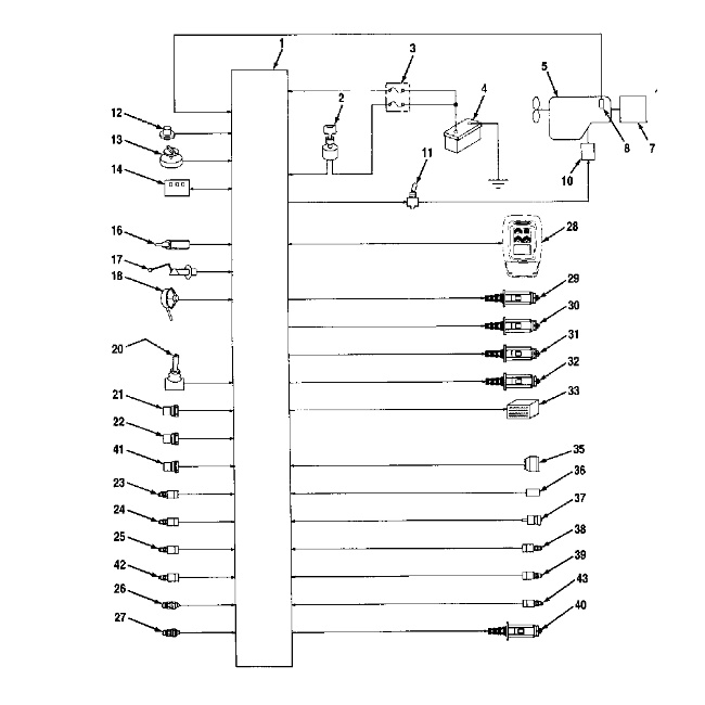
Diagram Of Inputs And Outputs Of The 325C and 330C Controller (1) Engine and Pump Controller (2) Starter Switch (3) Fuse Box (4) Battery (5) Engine (7) Pump (8) Speed sensor (10) Electronic Control Module (11) Backup Switch (12) Action Alarm (13) Engine Speed Dial (14) Switch Panel (16) Hydraulic Oil Temperature Sensor (17) Fuel Level Sensor (18) Alternator (20) One- touch Low Idle (21) Engine Oil Level Switch (22) Hydraulic Oil Level Switch (23) Implement Swing Pressure Switch (24) Travel Pressure Switch (right) (25) Travel Pressure Switch (left) (26) Pump Pressure Sensor (drive) (27) Pump Pressure Sensor (idle) (28) Monitor (29) Proportional Reducing Valve (30) Straight Travel Solenoid Valve (31) Travel Speed Solenoid Valve (32) Swing Parking Brake Solenoid Valve (33) Travel Alarm (35) Clogged Air Filter Switch (36) Clogged Hydraulic Oil Filter Switch (37) Engine Coolant Level Switch (38) Work tool pressure switch (39) Attachment Pedal Pressure Switch (40) Flow Control Valve (41) Water Separator Level Switch (42) Pressure switch for attachment (43) Attachment Pedal Pressure Switch |
|
|
|
|
|
|
|
| Illustration 4 | g01090443 |
|
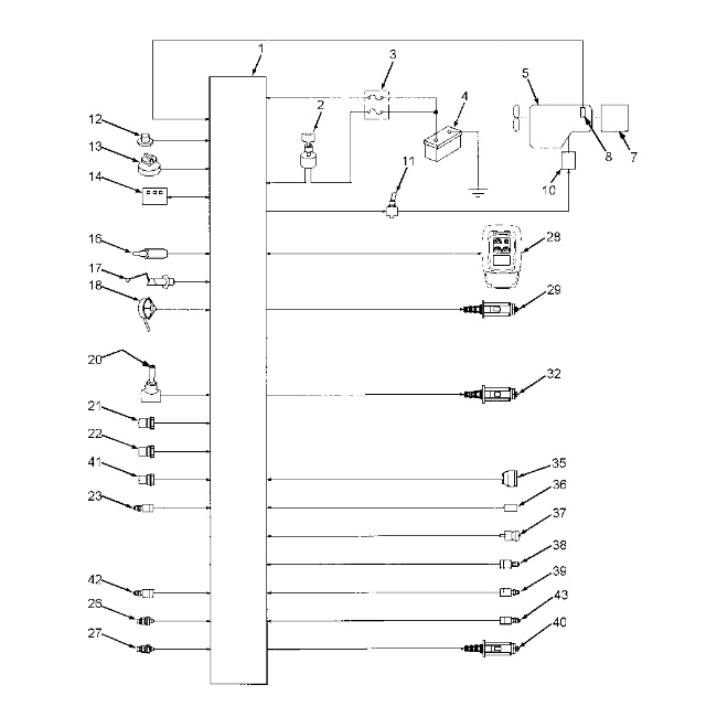
Diagram Of Inputs And Outputs Of The M325C MH Controller (1) Engine and Pump Controller (2) Starter Switch (3) Fuse Box (4) Battery (5) Engine (7) Pump (8) Speed sensor (10) Electronic Control Module (11) Backup Switch (12) Action Alarm (13) Engine Speed Dial (14) Switch Panel (16) Hydraulic Oil Temperature Sensor (17) Fuel Level Sensor (18) Alternator (20) One-touch Low Idle (21) Engine Oil Level Switch (22) Hydraulic Oil Level Switch (23) Implement Swing Pressure Switch (26) Pump Pressure Sensor (drive) (27) Pump Pressure Sensor (idle) (28) Monitor (29) Proportional Reducing Valve (32) Swing Parking Brake Solenoid Valve (35) Clogged Air Filter Switch (36) Clogged Hydraulic Oil Filter Switch (37) Engine Coolant Level Switch (38) Work tool pressure switch (39) Attachment Pedal Pressure Switch (40) Flow Control Valve (41) Water Separator Level Switch (42) Pressure switch for attachment (43) Attachment Pedal Pressure Switch |
|
Note: The 312C has one travel pressure switch. The 315C has one travel pressure switch. The 318C and 321C have two travel pressure switches.
Note: The Engine Control Module is on the 325C and on the 330C.
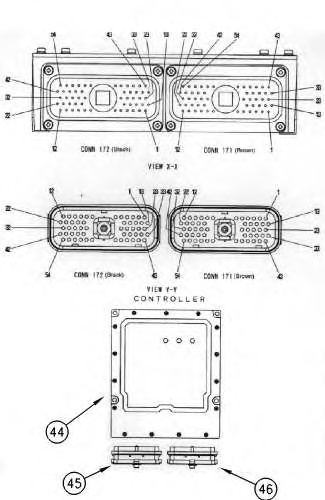
The controller is connected to the machine through two 54-pin connectors. The controller monitors the system through the inputs. Then, the controller adjustments the system through the outputs. The controller will control the hydraulic output of the pump by adjusting the power shift pressure according to the load on the machine.
|
|
|
|
|
|
| Illustration 5 | g00778730 |
|
Engine and Pump Controller (ECM) (44) Controller (45) Connector 1 (46) Connector 2 |
|
| Engine And Hydraulic Pump Control (Connector 1) (1) | ||
|---|---|---|
| No. 1 | Function | Type |
| 1 | +Unswitched Battery | Power |
| 2 | Ground | Ground |
| 4 | Air Heater Relay | Solenoid Output |
| 7 | Pressure Switch for 319C, 320C, and 320C LRR | Switch Input |
| 8 | Hammer Switch for 319C, 320C, and 320C LRR | Switch Input |
| 9 | Engine Speed Dial 1 | Operational Switch Input |
| 10 | Engine Speed Dial 2 | Operational Switch Input |
| 11 | One-touch Low Idle Switch | Switch Input |
| 12 | Mode Switch for the AEC | Switch Input |
| 13 | +Battery | Power |
| 14 | Ground | Ground |
| 16 | Overload protection | Switch Input |
| 17 | Implement Pressure Switch for 312C and 315C | Switch Input |
| 18 | Implement Control Line 2 | Output |
| 19 | Engine Speed Dial 3 | Operational Switch Input |
| 20 | Engine Speed Dial 4 | Operational Switch Input |
| 21 | Travel Mode Switch (2) | Switch Input |
| 22 | Travel Alarm Switch (2) | Switch Input |
| 23 | Key Start Switch | Switch Input |
| 28 | Implement Status 1 | Output |
| 29 | Control Lever Pressure Switch 319C, 320C, 321C, and 322C | Switch Input |
| 30 | Left Travel Pressure Switch 312C and 315C (2) | Switch Input |
| 31 | Coolant Level Switch | Switch Input |
| 32 | Hydraulic Oil Level Switch | Switch Input |
| 33 | Data Link + | Input/Output |
| 39 | Right Travel Pressure Switch (2) | Switch Input |
| 40 | Engine Oil Level Switch | Switch Input |
| 41 | Engine Oil Pressure Switch | Switch Input |
| 42 | Clogged Air Filter Indicator | Switch Input |
| 43 | Data Link Negative | Input/Output |
| 45 | Implement Status 3 | Output |
| 46 | Implement Status 4 | Output |
| 47 | Water Separator Level Switch (Not in 321C) |
Switch Input |
| 48 | Clogged Filter | Switch Input |
| 53 | Straight Travel Solenoid for 319C, 320C (2) | Switch Input |
| ( 1 ) | The connector contacts that are not listed are not used. The connector has 54 contacts. |
| ( 2 ) | Not on M325C MH |
| Engine And Hydraulic Pump Control (Connector 2) (1) | ||
|---|---|---|
| No.1 | Function | Type |
| 1 | Straight Travel Solenoid 319C, 320C, 320C LRR, 321C, and 322C (2) | Solenoid Output |
| 2 | Travel Speed Solenoid (2) | Solenoid Output |
| 4 | Swing Brake Solenoid | Solenoid Output |
| 6 | Fine Swing Switch | Switch Input |
| 7 | Power Shift Solenoid | Solenoid Output |
| 8 | Pump Flow Limitation Valve Solenoid |
Solenoid Output |
| 9 | Priority Control Valve | Solenoid Output |
| 13 | Travel Alarm (2) | Output |
| 14 | Mode Indicator for the AEC (2) | Output |
| 15 | Travel Mode Indicator (2) | Output |
| 16 | Negative Speed Sensor | Sensor Return |
| 17 | Neutral Start Relay for 322C | Solenoid Output |
| 19 | Solenoid Return | Ground |
| 20 | Solenoid Return | Ground |
| 21 | Solenoid Return | Ground |
| 22 | Solenoid Return | Ground |
| 23 | Action Alarm | Output |
| 24 | Travel Alarm Indicator (2) | Output |
| 25 | Engine Speed | Sensor Input |
| 29 | Coolant Temperature Sensor | Sensor Input |
| 30 | Fuel Level Sensor | Sensor Input (PWM) |
| 35 | Alternator Terminal “R” | Sensor Input (Voltage) |
| 36 | Feedback from the Governor | Sensor Input (PWM) |
| 37 | Main Pump Pressure Sensor | Sensor Input (PWM) |
| 39 | Hydraulic Oil Temperature Sensor | Sensor Input (PWM) |
| 44 | Governor Sensing | Sensor Input (Voltage) |
| 45 | Pump Delivery Pressure | Sensor Input (PWM) |
| 46 | Boom Hold | Sensor Input (PWM) |
| 47 | Backup Switch | Switch Input |
| 52 | +Battery for 319C, 320C, 320C LRR, and 322C | Power |
| ( 1 ) | The connector contacts that are not listed are not used. The connector has 54 contacts. |
| ( 2 ) | Not on M325C MH |
The controller actuates the governor actuator and the proportional reducing valve if the speed of the engine must change. Each input and output of the controller is connected to the machine harness through two 54-pin connectors.
Input/Output
The data link is a bidirectional component. The data link allows the controller to receive information and the controller can send information. The data link is designed to allow communication between the controller and the monitor. The data link is not a visible component. The data link consists of internal control circuits and the connecting harness wiring. The controller sends information through the data link to the monitor panel. The following list contains some examples: fuel level and engine coolant temperature. The controller also receives requested information from the monitor panel.
Input
Each input will describe the status of the machine system. Two types of inputs exist: switch type and sensor type. Switches provide an open or ground to the controller. Sensors provide a signal that changes to the controller.
Switch Input (Keyswitch)
The input of the key start switch connects to the controller through connector 1 and contact 23. The key start switch will provide input information to the controller about the status of the key start switch. The input for the key start switch is +battery when the key start switch is placed in the ON position.
Switch Input (Operational Type)
Each switch input will provide information about operator requests and machine systems. The condition of the system is sent to the controller through each input. The status of each input will be grounded, open or +battery. Each input of the controller will receive information from the switches that are located in the machine systems (pressure and temperature).
Sensor Input (Frequency)
An AC signal is present for the input of the frequency sensor. The AC signal is used to represent the speed of a machine system. For example, the engine speed sensor provides an AC signal to the controller. The controller measures the frequency (Hz) of the AC signals.
Sensor Input (Alternator)
The sensor input for the alternator connects to connector contact 2-35. A square wave signal is present at this input. The signal is used to represent the speed of the alternator. The controller measures the frequency (Hz) of the square wave signal. The controller uses this information to make determinations and the controller uses this information to monitor the output of the alternator. When an abnormal condition exists, the controller will alert the operator.
Sensor Input (PWM)
The controller receives a signal that is Pulse Width Modulated. This signal will represent the condition of a machine system. For example, the controller can monitor pressure. PWM sensors provide this information. The controller measures the duty cycle of the PWM signal. This signal will represent the information that is measured. When an abnormal condition exists, the controller will alert the operator.
Sensor Input (Voltage)
Connector “2” has an input for voltage sensing. A voltage is present. This voltage will represent the condition of a machine system. For example, the level of voltage is a condition that is monitored by the controller. Analog sensors or senders provide this information. The controller measures the voltage, which represents the measured information. The controller also uses this information to monitor machine systems. The controller alerts the operator if an abnormal condition exists.
Output
The controller responds to decisions by sending electrical signals through the various outputs. The outputs will create an action or the outputs will provide information. Three status indicators inside the controller that are connected to the monitor panel are outputs of the controller. These outputs are additional to the outputs that are listed in the table for the descriptions of the connector contacts. The monitor panel shows the operating status of the engine and pump control system and diagnostic information. This action could be energizing a solenoid, sounding an alarm or activating a motor. The controller will send an output to the following components:
- Governor actuator
- Proportional reducing valve for the power shift pressure
- Travel speed solenoid (Not on M325C MH)
- Action alarm (Not on M325C MH)
- Travel alarm (Not on M325C MH)
- Swing parking brake solenoid
- Proportional reducing valve for the tool mode
- Straight travel solenoid (Not on M325C MH)


