|
|
|
|
|
|
| Illustration 1 | g00685987 |
|
Diagram of Inputs and Outputs for Engine and Pump Regulation Models 312C through 322C (1) Engine speed dial (2) Engine and Pump Controller (3) Engine (4) Speed Sensor (5) Pump (6) Monitor (7) Governor lever (8) Hydraulic pump pressure sensor (right) (9) Governor actuator (10) Feedback sensor (11) Hydraulic pump pressure sensor (left) (12) Proportional reducing valve |
|
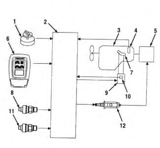
Note: The engine controller and the pump controller use one speed sensor. The engine ECM uses a different speed sensor.
|
|
|
|
|
|
| Illustration 2 | g00822636 |
|
This diagram is of Inputs and Outputs for the 325C and 330C. (1) Engine speed dial (2) Engine and Pump Controller (3) Engine (4) Speed Sensor (5) Pump (6) Engine Controller (7) Proportional reducing valve (8) Monitor (9) Hydraulic pump pressure sensor (right) (10) Hydraulic pump pressure sensor (left) |
|
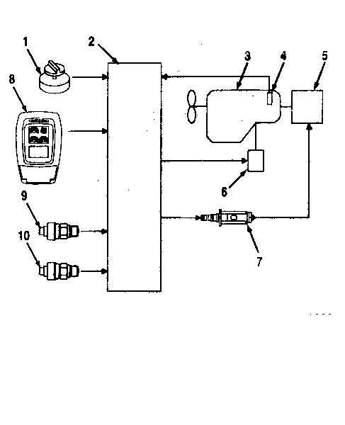
Note: The Engine Controller and the Pump Controller Use Separate Speed Sensors. The Engine ECM Uses a Separate Speed Sensor.
The controller (2) will determine the power shift pressure in order to control the pump. The controller determines the power shift pressure according to the position of the engine speed dial (1), the delivery pressure and the engine speed. When the power shift pressure is high, the output of the pump will decrease. When the power shift pressure is low, the output of the pump will increase. The power shift pressure will remain constant when the engine speed dial is set between 5 and 9. The power shift pressure will increase in increments as a setting of 4 or lower is selected. The power shift pressure will increase as the engine speed dial is set to a position lower than 5. The control of an underspeed condition is performed in position 10 of the engine speed dial.