The colors and the sizes of the wires that are shown in the Electric Circuit Diagram are identified and described in the following chart:
| Symbol | Color |
| BK | BLACK |
| BU | BLUE |
| BR | BROWN |
| GY | GRAY |
| GN | GREEN |
| OR | ORANGE |
| PK | PINK |
| PU | PURPLE |
| RD | RED |
| WH | WHITE |
| YL | YELLOW |
The following example will explain the wire identification:
- An example is listed. 308-YL-18
308 – The identification of the circuit
YL – The color of the wire
18 – This number represents the size of the wire (AWG) according to the standards that are set by the American Wiring Gauge. The gauge of the wire will be No. 16, if the gauge has not been specified.
|
|
|
|
|
|
| Illustration 1 | g00663022 |
|
Partial Diagram Of An Electrical Circuit (1) Harness symbol for harness “A” (2) Harness symbol for harness “L” |
|
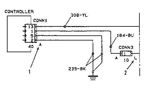
The harness symbol (1) or symbol (2) is shown on the connector or the terminal of a component. The symbol “A” identifies harness “A” and the symbol “L” identifies harness “L”.