Note: When additional safety is needed on machines that are equipped with a swing brake solenoid, disconnect the swing brake solenoid so that the swing brake remains engaged.
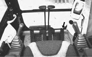
The device for activation for the work tool is the right foot pedal.
|
|
|
|
|
|
| Illustration 1 | g00988798 |
- Position the machine on level ground and stop the engine.
- Release the pressure in the hydraulic system. Refer to Testing and Adjusting, “Hydraulic System Pressure – Release” for the machine.
- Attach a 38000 kPa (5500 psi) pressure gauge to pressure tap (27) .
Note: Refer to Illustration 2 for the 320C and the 322C machines.
Note: Refer to Illustration 3 for the 325C machines.
- Close the stop valves that are mounted on each side of the stick. A stop valve is on each side of the stick. This will prevent oil flow to the work tool during this procedure.
|
|
|
|
|
|
| Illustration 2 | g01000946 |
|
Pump compartment for the 320C and the 322C (26) Pressure tap (idler pump) (27) Pressure tap (drive pump) (37) Pressure tap (power shift) |
|

|
|
|
|
|
|
| Illustration 3 | g01000947 |
|
Pump compartment for the 325C (26) Pressure tap (idler pump) (27) Pressure tap (drive pump) (37) Pressure tap (power shift) |
|

|
|
|
|
|
|
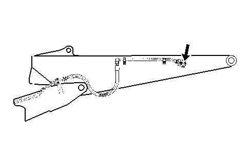
| Illustration 4 | g00994459 |
|
Stop valve |
|
- Start the engine.
- Place the machine controls at the following settings: engine speed dial “10” and AEC switch OFF. Refer to Testing and Adjusting, “Engine Performance – Test – Engine Speed” for the machine for engine rpm settings.
- Verify that the pilot pressure is set to the proper specification that is found in Testing and Adjusting, “Relief Valve (Pilot) – Test and Adjust” for the machine.
- Warm the hydraulic oil to 55° ± 5°C (131° ± 9°F).
- Verify that the main relief valve is set to the proper specification that is found in Testing and Adjusting, “Relief Valve (Main) – Test and Adjust” for the machine.
- Perform the calibration for the proportional solenoid valve for negative flow control. Refer to Testing and Adjusting, “System 1: Solenoid Valve (Proportional Reducing) – Calibrate (Negative Flow Control)” for the Tool Control System.
- Verify that the proportional reducing valve (power shift) is properly calibrated. If necessary, see Testing and Adjusting, “Proportional Reducing Valve – Calibrate (Power Shift)” for the Engine and Pump Control System.
- Press and hold the device for activation.
- At pressure tap (27) , check the pressure setting for the line relief valve that is mounted near the boom foot .
- Release the device for activation.
- The relief valve pressure setting for the work tool is 20600 ± 1500 kPa (2990 ± 220 psi). If the relief valve pressure setting for the work tool is not within the specification, adjust the relief valve pressure setting for the work tool 3447 kPa (500 psi)and 5171 kPa (750 psi) above the operating pressure setting of the tool.
Note: Refer to the manufacturer of the tool.
- In order to adjust the relief valve for the work tool, loosen the locknut. Then turn the adjustment screw until the pressure gauge reading at pressure tap (27) is 20600 ± 1500 kPa (2990 ± 220 psi).
Note: Turning the adjustment screw clockwise increases the pressure. Turning the adjustment screw counterclockwise decreases the pressure.
Note: Always make final pressure adjustments on pressure rise.
|
|
|
|
|
|
| Illustration 5 | g00989153 |
|
(15) Locknut (16) Adjustment screw |
|
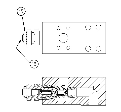
- Tighten locknut (15) to a torque of 50 ± 10 N·m (37 ± 7 lb ft).