This calibration procedure is used in order to record the correction data of the proportional solenoid valve for the tool control. This calibration should be done at the following times: replacement of the NFC solenoid valve, replacement of the ECM, flash new software and adjustments to the horsepower controls on the pump.
Before this procedure is performed , ensure that the following requirements are met:
- Verify that the governor actuator is properly calibrated. If necessary, see Testing and Adjusting, “Governor Actuator – Calibrate” for the Tool Control System.
- Verify that the pilot pressure is set to the proper specification that is found in Testing and Adjusting, “Relief Valve (Pilot) – Test and Adjust” for the machine.
- Verify that the main relief valve is set to the proper specification that is found in Testing and Adjusting, “Relief Valve (Main) – Test and Adjust” for the machine.
- Verify that the proportional reducing valve (power shift) is properly calibrated. If necessary, see Testing and Adjusting, “Proportional Reducing Valve – Calibrate (Power Shift)” for the Engine and Pump Control System.
There are two methods for calibrating the proportional solenoid valve for negative flow control. One method uses a flow meter and a pressure gauge. This method is more accurate. The other method uses only a pressure gauge. This method is less accurate. Both methods are described below.
Note: The less accurate method which uses only a pressure gauge is used only when a flow meter is not available.
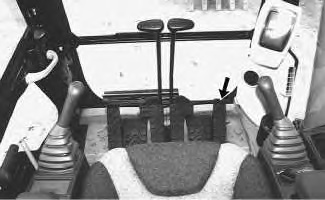
The device for activation for the work tool is the right foot pedal.
|
|
|
|
|
|
| Illustration 1 | g00988798 |
Calibration With a Pressure Gauge and a Flow Meter
- Position the machine on level ground and stop the engine.
Note: When additional safety is needed on machines that are equipped with a swing brake solenoid, disconnect the swing brake solenoid so that the swing brake remains engaged.
- Release the pressure in the hydraulic system. Refer to Testing and Adjusting, “Hydraulic System Pressure – Release” for the machine.
- Install a 400 L (106 US gal) flow meter in the hydraulic line to the tool.
Note: Table 1 lists the parts which appear in 2.
Table 1 TOOL CHART FOR FLOW TEST Item Number Part Number Part Description Quantity 10 4C-9910 Flow Meter 1 11 6K-6307 O-ring seal 2 12 8C-9026 Adapter 2 13 7M-8485 O-ring seal 8 14 4C-6482 Nipple 4 9U-5086 Optional Dust Cap 4 15 4C-6481 Coupler 4 9U-5084 Optional Dust Plug 4 16 4C-8767 Coupling 4 17 5P-1010 Sleeve 4 18 5P-0201 XT-5 Hose 3.5 m (12 ft)
2 19 8T-4194 Bolt 4 20 8T-4223 Hard Washer 2 21 1P-5767 Half Flange 4 22 1U-8293 Adapter 2 23 1P-3704 Rectangular Seal 2 28 6V-4143 Coupler 2 29 6V-3014 Hose 1 30 6V-3989 Nipple 1 31 8T-0861 Pressure Gauge 1 - Connect one end of hydraulic line (32) for the flow meter to the connection on the left side of the flow meter (input port). Connect the other end of this hydraulic line to the port on the supply side of the stick.
Illustration 2 g00990081 (24) Port on supply line for work tool
(25) Port on return line for work tool
(26) Pump pressure tap
(27) Pump pressure tap
(35) Main pump
Illustration 3 g00990153 (10) Flow meter
(32) Supply line for work tool
(33) Return line for work tool
(34) Load valve for flow meter
- Connect one end of the second hydraulic line (33) for the flow meter to the connection on the top of the flow meter (output port). Connect the other end of this hydraulic line to the port on the return side of the stick.


- Install a 40000 kPa (5800 psi) pressure gauge on pressure tap (26) .
Note: Refer to Illustration 4 for the 320C and the 322C machines.
Note: Refer to Illustration 5 for the 325C machines.
|
|
|
|
|
|
| Illustration 4 | g01000946 |
|
Pump compartment for the 320C and the 322C (26) Pressure tap (idler pump) (27) Pressure tap (drive pump) (37) Pressure tap (power shift) |
|

|
|
|
|
|
|
| Illustration 5 | g01000947 |
|
Pump compartment for the 325C (26) Pressure tap (idler pump) (27) Pressure tap (drive pump) (37) Pressure tap (power shift) |
|

- Place the backup switch in the AUTO position.
- Start the engine.
- Move the engine speed dial to position 10.
- Increase the oil temperature to 50 °C (122 °F).
- Be sure that the tool that is selected for use is a work tool that provides one pump flow. The default programming for “TOOL#2” is for one pump operation. Refer to Testing and Adjusting, “Work Tool – Select” for the Tool Control System. If “TOOL#2” has been reprogrammed for two pump flow, select a tool that provides one pump flow.
- Enter the service mode on the monitor. See Testing and Adjusting, “Service Mode – Enter” for the Tool Control System for step-by-step instructions on entering the service mode.
|
|
|
|
|
|
| Illustration 6 | g00935640 |
|
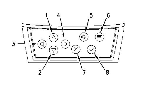
Monitor Panel (1) Up key (2) Down key (3) Left key (4) Right key (5) Set key (6) Menu key (7) Cancel key (8) OK key |
|
- After entering service mode, the above screen should be displayed.
Note: The fourth line will indicate the sales model of the excavator.
|
|
|
|
|
|
| Illustration 7 | g01000769 |

- Press down key (2) in order to highlight line 2. Select “CALIBRATION” with left key (3) or right key (4) . This is shown in illustration 8.
|
|
|
|
|
|
| Illustration 8 | g00694795 |

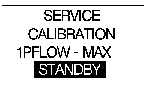
- Press down key (2) in order to highlight line 3. The calibration device name will appear on line 3. Press the keys for direction in order to scroll through the calibrations that are available. Change the calibration device name to “1PFLOW”. The calibration must be performed at the higher flow rate (“1PFLOW – MAX”), and the calibration must be performed at the lower flow rate (“1PFLOW – MIN”). Refer to Table 2 for the proper flow rate of the machine that is being tested.
Table 2 Flow Rates
Flow rates at
16000 ± 500 kPa (2320 ± 72 psi)One Pump
MAXOne Pump
MINTwo Pump
MAXTwo Pump
MIN320C and 322C 180 ± 3 L (48 ± 0.8 US gal) 120 ± 3 L (32 ± 0.8 US gal) NA NA 325C 200 ± 3 L (53 ± 0.8 US gal) 140 ± 3 L (37 ± 0.8 US gal) NA NA
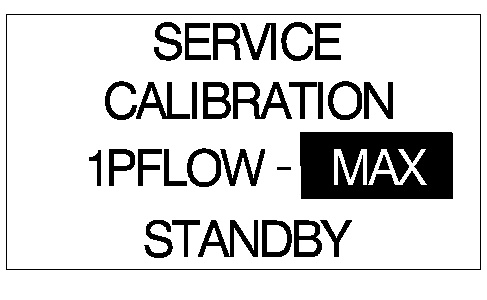
- Perform the “1PFLOW – MAX” calibration first. In order to change from the “MIN” calibration to the “MAX” calibration, highlight line 3. Press menu key (6) in order to move the portion of line 3 that is highlighted to the right. This is shown in illustration 9. Press left key (3) or right key (4) in order to change the calibration from “MIN” to “MAX”.
|
|
|
|
|
|
| Illustration 9 | g00947067 |
- Press OK key (8) . The calibration value is now highlighted on line 4. The machine ECM increases the engine speed to “10”.
- Press the device for activation 3 times and release the device for activation 3 times.
- Press and hold the device for activation.
- Adjust the setting of the load valve on the flow meter (34) and observe pressure gauge (14) . Adjust the setting until the pressure gauge indicates 16000 ± 250 kPa (2320 ± 36 psi).
Pump pressure is affected by the flow and the open rate of the load valve on the flow meter (34) . The load valve on the flow meter (34) must be adjusted when a change of calibration is made. When you adjust the calibration value and the open rate of the load valve on the flow meter (34) setting, always return the tool to the neutral position and repeat the calibration.
- Refer to Table 2 and observe the flow meter in order to verify that the flow rate is within the proper specifications.
- If the flow is not within the proper specifications, the machine must be adjusted. Proceed to steps 12 through 18.
- Release the right foot pedal. DO NOT change the setting of the load valve on the flow meter (34) .
- Adjust the value on line 4 of the monitor. Press left key (3) or right key (4) in order to adjust the value on line 4.
It is possible to correct the flow control pressure from “+60” to “-60” by using the monitor.
The flow changes approximately 2 L/min (0.5 US gpm) when the left key (3) or the right key (4) is pressed one time.
- Press and hold the device for activation.
- If the pressure is out of the proper range, adjust the load valve on the flow meter (34) until the pressure gauge indicates 16000 kPa (2320 psi).
- Refer to Table 2 and observe the flow meter in order to verify that the flow rate is within the proper specifications.
- Repeat steps 12 through 16 until the flow rate in step 16 is obtained with no adjustments of the monitor or the load valve for several repetitions.
Note: Press and hold the device for activation for a few seconds in order to allow the hydraulic system to stabilize before repeating the steps.
- When the reading is within the proper range, continue to hold the device for activation and press set key (5) in order to save the value. Line 3 will automatically be highlighted. The “1PFLOW – MIN” calibration will now be performed.
Note: If set key (5) is not pressed the calibration will not be saved.