Note: Each of the five work tools have separate values for each parameter that is used. Parameters 201 through 403 are used when the system of the machine is programmed as “Special Application”. Refer to Testing and Adjusting, “Machine Tool Control System – Select” for the Tool Control System for more information. The list of available parameters are described in more detail in table 2.
| List of Available Parameters | ||
|---|---|---|
| Monitor | ET | Parameter Description |
| 001 | “Tool Program Name” | Each tool has a descriptive name that is programmable. The name may contain 14 characters. |
| 002 | “Maximum Throttle Dial” | This item is the upper limit of the engine speed dial that is used when the tool is operating. When a tool is operating, the controller compares the current speed of the engine to this maximum setting. If the engine speed is higher than the setting, the engine speed is reduced to the proper level. This parameter may be turned ON with parameter 003. (1) |
| 003 | “Throttle Dial Flow Control” | This parameter is used in order to control parameter 002. Parameter 003 is set to ON or this parameter is set to OFF. (1) |
| 004 | “Underspeed Enable” | This parameter enables the function for underspeed control. If a tool is not operating properly and parameter 004 is turned ON, disable this parameter. (1) |
| 005 | “Two Pump Flow Combine Enable” | This parameter enables combined hydraulic flow with two pumps. This parameter should always be set to “ENABLE” for all systems that are covered by this manual. |
| 006 | “Initial Med Pressure Circuit Main Pump Power Reduction” | Parameters 006 and 007 are used in order to control the hydraulic power when the medium pressure circuit is activated. |
| 007 | “Total Med Pressure Circuit Main Pump Power Reduction” | |
| 008 | “One Way/Two Way Valve Mode” | This parameter controls the solenoid for one-way flow or two-way flow on the “EC3” check valve. When the solenoid is energized, the one-way flow returns the hydraulic oil to the tank through the check valve. |
| 009 | “Variable Relief Valve #1 Pressure” | This parameter sets the relief pressure of the “ER1” relief valve. |
| 010 | “Variable Relief Valve #2 Pressure” | This parameter sets the relief pressure of the “ER2” relief valve. |
| 015 | “Tool Program F2 Type Valve Max Flow Derate Pressure” | Parameters 015, 016 and 017 are used in order to define the set points for the clench pressure circuit. |
| 016 | “Tool Program F2 Type Valve Max Flow Start Pressure” | |
| 017 | “Tool Program F2 Type Valve Max Flow End Pressure” | |
| 018 | “Multiple Operation Maximum Extend Pilot Pressure for Attachment Valve #1” | This parameter is used in order to set the upper limit of the pilot pressure for the extension stroke of the attachment valve when the work tool and the implement are operated at the same time. This parameter is used only on machines that are equipped with a System 14 or a System 17. |
| 019 | “Multiple Operation Maximum Retract Pilot Pressure for Attachment Valve #1” | This parameter is used in order to set the upper limit of the pilot pressure for the retraction stroke of the attachment valve when the work tool and the implement are operated at the same time. This parameter is used only on machines that are equipped with a System 14 or a System 17. |
| 020 | “Multiple Operation Maximum Extend Pilot Pressure for Attachment Valve” | This parameter is used in order to set the upper limit of the pilot pressure for the extension stroke of the auxiliary valve when the work tool and the implement are operated at the same time. This parameter is used only on machines that are equipped with a System 14 or a System 17. |
| 021 | “Multiple Operation Maximum Retract Pilot Pressure for Attachment Valve” | This parameter is used in order to set the upper limit of the pilot pressure for the retraction stroke of the auxiliary valve when the work tool and the implement are operated at the same time. This parameter is used only on machines that are equipped with a System 14 or a System 17. |
| 101 | “Attachment Valve #1 Flow Setting” | This parameter is the primary flow requirement for the work tool. This value is measured in liters per minute. |
| 102 | “Attachment Valve #1 Multi-Oper. Additional Flow” | When the tool is operating and another hydraulic function is initiated, this parameter regulates the amount of additional flow that is provided in order to perform multiple functions at the same time. This parameter is programmed in liters per minute. |
| 103 | “Tool Program Valve #1 Nominal Pressure” | This parameter improves the accuracy when the flow is calculated. The value is the working pressure setting plus the pressure loss of the hydraulic system 2000 kPa (290 psi). For example, when the machine is equipped with a tool with a working pressure setting of 14000 kPa (2050 psi), use 16000 kPa (2300 psi) as this value. |
| 104 | “Attachment Valve #1 Open Time” | This parameter controls the ramp up time. This is the time that is required in order to move the spool in the attachment control valve to either open position. |
| 105 | “Attachment Valve #1 Close Time” | This parameter controls the ramp down time. This is the time that is required in order to move the spool in the attachment control valve to the center position. |
| 106 | “Attachment Valve #1 Maximum Extend Pressure” | This parameter controls the maximum pilot pressure to the attachment control valve for extension. |
| 107 | “Attachment Valve #1 Maximum Retract Pressure” | This parameter controls the maximum pilot pressure to the attachment control valve for retraction. |
| 201 | “Attachment Valve #2 Flow Setting” | This parameter is the primary flow requirement for the work tool. This value is measured in liters per minute. |
| 202 | “Attachment Valve #2 Multi-Oper. Additional Flow” | When the tool is operating and another hydraulic function is initiated, this parameter regulates the amount of additional flow that is provided in order to perform multiple functions at the same time. This parameter is programmed in liters per minute. |
| 203 | “Tool Program Valve #2 Nominal Pressure” | This parameter improves the accuracy when the flow is calculated. The value is the working pressure setting plus the pressure loss of the hydraulic system 2000 kPa (290 psi). For example, when the machine is equipped with a tool with a working pressure setting of 14000 kPa (2050 psi), use 16000 kPa (2300 psi) as this value. |
| 301 | “Attachment Valve #3 Flow Setting” | This parameter is the primary flow requirement for the work tool. This value is measured in liters per minute. |
| 302 | “Attachment Valve #3 Multi-Oper. additional Flow” | When the tool is operating and another hydraulic function is initiated, this parameter regulates the amount of additional flow that is provided in order to perform multiple functions at the same time. This parameter is programmed in liters per minute. |
| 303 | “Tool Program Valve #3 Nominal Pressure” | This parameter improves the accuracy when the flow is calculated. The value is the working pressure setting plus the pressure loss of the hydraulic system 2000 kPa (290 psi). For example, when the machine is equipped with a tool with a working pressure setting of 14000 kPa (2050 psi), use 16000 kPa (2300 psi) as this value. |
| 304 | “Attachment Valve #3 Open Time” | This parameter controls the ramp up time. This is the time that is required in order to move the spool in the auxiliary control valve (medium pressure) to either open position. This parameter is used on machines that are equipped with System 14 or System 17 when “Tool#2” and “Tool#4 ” is selected. |
| 305 | “Attachment Valve #3 Close Time” | This parameter controls the ramp down time. This is the time that is required in order to move the spool in the auxiliary control valve (medium pressure) to the center position. This parameter is used on machines that are equipped with System 14 or System 17 when “Tool#2” and “Tool#4 ” is selected. |
| 306 | “Attachment Valve #3 Maximum Extend Pressure” | This parameter is the maximum pilot pressure to the auxiliary control valve (medium pressure) for extension. This parameter is used on machines that are equipped with System 14 or System 17 when “Tool#2” and “Tool#4 ” is selected. |
| 307 | “Attachment Valve #3 Maximum Retract Pressure” | This parameter is the maximum pilot pressure to the auxiliary control valve (medium pressure) for retraction. This parameter is used on machines that are equipped with System 14 or System 17 when “Tool#2” and “Tool#4 ” is selected. |
| 401 | “Attachment Valve #4Flow Setting” | This parameter is the primary flow requirement for the work tool. This value is measured in liters per minute. |
| 402 | “Attachment Valve #1 Multi-Oper. Additional Flow” | When the tool is operating and another hydraulic function is initiated, this parameter regulates the amount of additional flow that is provided in order to perform multiple functions at the same time. This parameter is programmed in liters per minute. |
| 403 | “Tool Program Valve #4 Nominal Pressure” | This parameter improves the accuracy when the flow is calculated. The value is the working pressure setting plus the pressure loss of the hydraulic system 2000 kPa (290 psi). For example, when the machine is equipped with a tool with a working pressure setting of 14000 kPa (2050 psi), use 16000 kPa (2300 psi) as this value. |
| ( 1 ) | Normally, these parameters are not changed. |
Programming The Five Tools
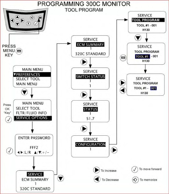
In order to program any of the parameters of the machine, first enter “Service Mode” on the monitor. This procedure is described in full in Testing and Adjusting, “Service Mode – Enter” for the Tool Control System. After entering the password for the service mode, the following screen will be displayed on the monitor:
|
|
|
|
|
|
| Illustration 1 | g01000769 |

|
|
|
|
|
|
| Illustration 2 | g01008955 |
|
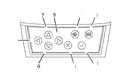
Monitor Panel (7) Up key (8) Left key (9) Right key (10) Down key (11) Cancel key (12) Set key (13) Menu key (14) OK key |
|
Use down key (10) in order to highlight line 2. Use right key (9) and scroll until “CONFIGURATION” is displayed on the monitor. If the right key (9) is pressed again, “TOOL PROGRAM” will be displayed on the monitor.
|
|
|
|
|
|
| Illustration 3 | g01009235 |
|
|
|
|
|
|
| Illustration 4 | g00779463 |
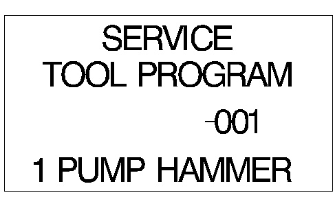
After you reach the “TOOL PROGRAM” screen, press down key (10) in order to highlight the third line. The left side of the line (“TOOL#1”) is initially highlighted. This is shown in illustration 4. Press left key (8) or right key (9) in order to scroll through the five tools that are available. After you reach the desired tool, press menu key (13) in order to highlight the right side of the line. This is shown in illustration 5.
|
|
|
|
|
|
| Illustration 5 | g00779470 |

In illustration 5, “TOOL#1” is the tool that is being programmed. The value for parameter 001 is on the fourth line. Press down key (10) in order to change the fourth line. If you want to move to the next parameter, press right key (9) when “001” is highlighted. The portion of the line that is highlighted will change to “002”. The value for the new parameter will be displayed on the fourth line.
Setting The Name of the Tool
It is possible to set up names for each of the five tools. Parameter 001 is the descriptive name of the tool. These names consist of 14 letters of your choosing. The following characters are valid in a name: (space), !, #, *, +, -, ., /, 0-9, :, ;, =, ? and A-Z.
After you reach “Parameter 001”, press down key (10) in order to highlight the fourth line. Use the keys for direction in order to change the value. Press set key (12) in order to save the new value. Line 3 will be highlighted after the value is saved.
All of the other parameters are programmed in the same manner.