|
|
|
|
|
|
| Illustration 1 | g00674170 |
|
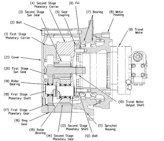
Final drive (1) Planetary carrier (first stage) (2) Bolt (3) Sun gear (second stage) (4) Planetary carrier (second stage) (5) Gear coupling (6) Pin (7) Bearing (8) Motor housing (9) Travel motor (10) Travel motor output shaft (11) Housing (sprocket) (12) Bolt (13) Planetary shaft (second stage) (14) Planetary gear (second stage) (15) Roller bearing (16) Ring gear (17) Planetary gear (first stage) (18) Planetary shaft (first stage) (19) Roller bearing (20) Sun gear (first stage) (21) Cover |
|
The final drive reduces the rotational speed of travel motor (9). Travel motor output shaft (10) is splined to first stage sun gear (20) of the final drive.
The final drive consists of two groups. The first group is the two stages of the planetary gears. The second group is the output group.
The two stages of the planetary gears contain the following components.
- The components of the first stage reduction are planetary carrier (1), ring gear (16), planetary gear (17) and sun gear (20) .
- The components of the second stage reduction are sun gear (3), planetary carrier (4), planetary gear (14) and ring gear (16) .
The output group is described in the following manner. The rotation of housing (11) develops output torque that is used to drive the track. Housing (11), ring gear (16) and cover (21) are held together with bolts (2). Housing (11), ring gear (16) and cover (21) are held in position by bearing (7). Housing (11) and cover (21) rotate with ring gear (16) .
The planetary gears reduce the travel speed. The travel speed is reduced by the ratio of teeth of the sun gear and the ring gear. The compact travel drive offers a greater reduction ratio when the sun gear is incorporated in the ring gear.
Planetary Gear Operation
Sun gear (20) is splined to output shaft (10). The rotation of travel motor output shaft (10) is transferred to sun gear (20). Sun gear (20) rotates clockwise. The travel drive assembly operates in the following manner.
|
|
|
|
|
|
| Illustration 2 | g00722185 |
|
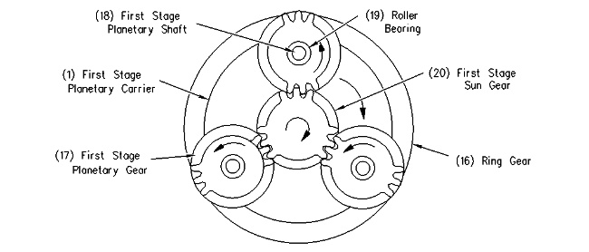
First stage reduction group (1) Planetary carrier (first stage) (16) Ring gear (17) Planetary gear (first stage) (18) Planetary shaft (first stage) (19) Roller bearing (20) Sun gear (first stage) |
|
Sun gear (20) engages with planetary gears (17) in the first stage reduction group. Planetary gears (17) rotate counterclockwise as sun gear (20) rotates clockwise. Planetary gears (17) also engage with ring gear (16). Planetary gears (17) advance clockwise around the teeth of ring gear (16). Planetary gears (17) are mounted to planetary carrier (1) by planetary shafts (18) and roller bearings (19). The assembly of planetary carrier (1), planetary gears (17), planetary shafts (18) and roller bearings (19) rotates clockwise.
|
|
|
|
|
|
| Illustration 3 | g00722193 |
|
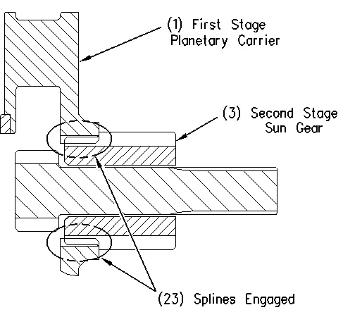
Splines in engagement (1) Planetary carrier (first stage) (3) Sun gear (second stage) (23) Splines in engagement |
|
The rotation of planetary carrier (1) is transferred to sun gear (3) of the second stage. The splines of planetary carrier (1) meshes with the teeth of sun gear (3). Sun gear (3) rotates clockwise.
The splines on planetary carrier (4) of the second stage engage with the teeth on the outer circumference of gear coupling (5). Gear coupling (5) is held to motor housing (8) through pins (6) and bolts (12). Motor housing (8) is bolted to the track frame.
Planetary carrier (4) does not rotate. Planetary shaft (13) does not rotate. The axis of planetary gear (14) is stationary. This causes ring gear (16) to rotate counterclockwise.
Ring gears (16) and housing (11) are held together with bolts (2). The sprocket wheel is bolted to housing (11). The torque of sun gear (3) is transferred to housing (11). This causes the sprocket to rotate counterclockwise. The right track rotates in the forward direction.


