The auxiliary pedal control may be used for straight travel operation. The auxiliary pedal control controls the travel motors from one pilot control valve.
The following components are the main components of the auxiliary pedal control:
- Hydraulic control
- Pilot oil lines
|
|
|
|
|
|
| Illustration 1 | g01555234 |
|
(1) Cab floorplate (2) Pedal assembly (3) Pilot control valve |
|
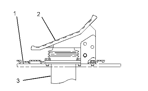
The hydraulic control is bolted to cab floorplate (1) on the right side of the travel pedals. The hydraulic control consists of pedal assembly (2) and pilot control valve (3) .
The auxiliary pedal is operated by depressing the pedal forward or backward. Depressing the pedal forward causes the machine to travel straight forward. Depressing the pedal backward causes the machine to travel in straight reverse.
|
|
|
|
|
|
| Illustration 2 | g01555253 |
|
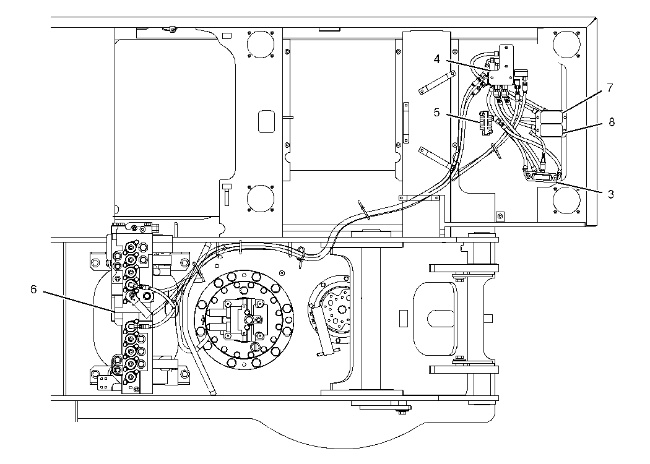
Pilot lines and pilot control valves for travel operation. (3) Pilot control valve (auxiliary pedal) (4) Hydraulic shuttle valve (resolver valve) (5) Manifold for pilot supply oil (6) Main control valve (7) Pilot control valve (left travel) (8) Pilot control valve (right travel) |
|
|
|
|
|
|
|
| Illustration 3 | g01553753 |
|
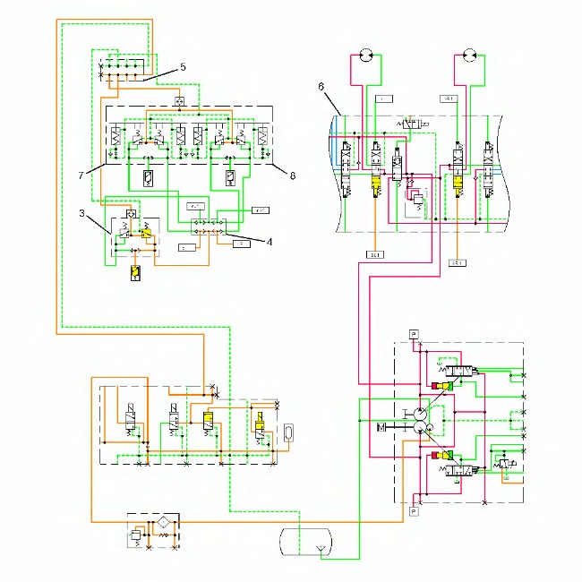
Partial Schematic (Forward Travel) (3) Pilot control valve (auxiliary pedal) (4) Hydraulic shuttle valve (resolver valve) (5) Manifold for pilot supply oil (6) Main control valve (7) Pilot control valve (left travel) (8) Pilot control valve (right travel) |
|
|
|
|
|
|
|
| Illustration 4 | g01555334 |
|
Pilot Control Valve (9) Pilot oil supply port (10) Passage (11) Rod (12) Seat (13) Spring (14) Spring (15) Stem (16) Passage (17) Port |
|
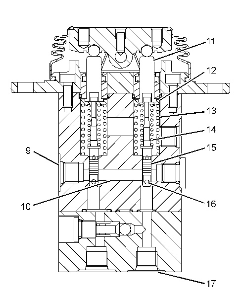
The description that follows is for forward travel. The operation is similar for reverse travel.
When the hydraulic activation control valve is activated, pilot oil is supplied to manifold (5) . Pilot oil flows from manifold (5) to port (9) of pilot control valve (3) . The pilot oil at port (9) flows into passage (10) .
When pedal (2) is depressed forward, rod (11) and seat (12) are pushed down against the force of springs (13) and (14) . When stem (15) moves down, passage (16) is opened to passage (10) .
As passage (16) is opened, the pilot oil in passage (10) flows through passage (16) to port (17) .
The pilot oil flows from port (17) through hydraulic shuttle valve (4) .
|
|
|
|
|
|
| Illustration 5 | g01555337 |
|
Hydraulic Shuttle Valve (18) Inlet port for straight travel (19) Inlet port for right travel (20) Inlet port for left travel (21) Outlet port (22) Outlet port (23) Check ball (24) Check ball |
|
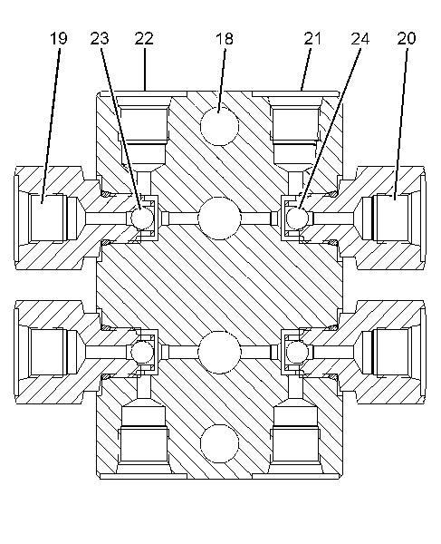
The pilot oil flows to port (18) . The pilot oil pressure pushes check ball (23) and check ball (24) against port (19) and port (20) . The check balls prevent pilot oil flow from port (19) and port (20) . The pilot oil flows out of port (21) and port (22) .
The pilot oil flows to the main control valve. The pilot oil shifts both of the travel control valves which provides main pump oil equally to the travel motors. The machine travels forward.