|
|
|
|
|
|
| Illustration 1 | g02641760 |
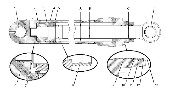
| Specification for 289-8031 Stick Cylinder Gp | |||
| Item | Qty | Part | Specification Description |
| 1 | During the press fit, insert the bushing (1) in the cap assembly, and in the rod assembly with the tapered side first. Bushing is one of the following part numbers: |
||
| 2 | 241-7342 Bushing | Inside diameter before assembly is 90.16 ± 0.02 mm (3.550 ± 0.001 inch). Installation depth in the cap assembly is 9.85 ± 0.30 mm (0.388 ± 0.012 inch). Installation depth in the rod assembly is 10.0 ± 0.3 mm (0.39 ± 0.01 inch). |
|
| 2 | 290-9183 Bushing | Inside diameter before assembly is 90.25 ± 0.04 mm (3.553 ± 0.002 inch). Installation depth in the cap assembly is 9.85 ± 0.30 mm (0.388 ± 0.012 inch). Installation depth in the rod assembly is 10.0 ± 0.3 mm (0.39 ± 0.01 inch). |
|
| 2 | 1 | 7Y-4956 Locknut | Use any one of the following methods to tighten the locknut: Before assembly, lubricate the threads of the locknut (2) with 309-6932 Hydraulic Oil all around and then torque to 15500 ± 800 N·m (11432 ± 590 lb ft). Or Lubricate the threads of the locknut (2) with molybdenum disulfide and then torque to 11500 ± 600 N·m (8482 ± 443 lb ft). |
| 3 | 2 | 191-5604 Ring | Lubricate the inside diameter and the outside diameter with clean grease. |
| 4 | 1 | 9X-3607 Seal As | Lubricate the inside diameter and the outside diameter with clean grease. |
| 5 | 1 | 191-5605 Ring | Lubricate the inside diameter and the outside diameter with clean grease. |
| A | 1 | 289-8032 Hydraulic Cylinder | Bore is 170.00 ± 0.10 mm (6.693 ± 0.004 inch). |
| B | 1 | 289-8037 Rod As | Diameter is 114.93 ± 0.03 mm (4.525 ± 0.001 inch). |
| C | 1 | 358-8526 Head | Bore is 115.63 ± 0.03 mm (4.552 ± 0.001 inch). |
| 6 | 1 | 107-6933 Stop | Free linear movement of the stop after assembly is 0.50 ± 0.26 mm (0.020 ± 0.010 inch). |
| 7 | 2 | 095-0930 Retaining Ring | Maximum outside diameter of the retaining rings after assembly is 81.0 mm (3.19 inch). |
| 8 | 1 | 231-6843 Seal Ring | The slit of the seal ring must turn in the direction of the piston. |
| 9 | 1 | 191-5644 Bushing | Outside diameter is 120.148 ± 0.032 mm (4.7302 ± 0.0013 inch). Thickness is 1.2 ± 0.3 mm (0.05 ± 0.01 inch). |
| 10 | 1 | 324-9484 Buffer Seal | Lubricate the sealing lip of the buffer seal lightly with the lubricant that is being sealed. |
| 11 | 1 | 324-9486 U-Cup Seal | Lubricate the sealing lip of the U-cup seal lightly with the lubricant that is being sealed. |
| 12 | 1 | 191-5648 Lip Type Seal | Lubricate the sealing lip of the lip type seal lightly with the lubricant that is being sealed. |
| 13 | – | – | Before assembly, apply green Loctite 609 to the wiper seal groove. |
