Table 1
| “Cylinder Drift – Check (Empty Bucket)” |
| Item |
Cylinder Position |
New |
Rebuild |
Service Limit |
Actual |
| Boom Cylinder |
Extended |
6.0 mm (0.24 inch) or less |
12.0 mm (0.47 inch) or less |
24.0 mm (0.94 inch) or less |
|
| Stick Cylinder |
Retracted |
10.0 mm (0.39 inch) or less |
15.0 mm (0.59 inch) or less |
25.0 mm (0.98 inch) or less |
|
| Extended |
25.0 mm (0.98 inch) or less |
30.0 mm (1.18 inch) or less |
40.0 mm (1.57 inch) or less |
|
| Bucket Cylinder |
Extended |
10.0 mm (0.39 inch) or less |
15.0 mm (0.59 inch) or less |
25.0 mm (0.98 inch) or less |
|
| Retracted |
20.0 mm (0.79 inch) or less |
25.0 mm (0.98 inch) or less |
35.0 mm (1.38 inch) or less |
|
The performance level of the cylinder, the cylinder seals, and the overload relief valves for the implements can be determined with the following procedure.
Note: The machine configuration that is used during this test can affect the results of this test. Refer to Testing and Adjusting, “Operational Checks” for the machine configurations that were used for this test.
Note: The relief valve pressure settings must be set to the relief valve pressure specification before performing this operational check. Refer to Testing and Adjusting, “Specifications”.
Table 2
| Required Tools |
| Description |
Qty |
| Measuring Tape |
1 |
| Stopwatch |
1 |
|
|
|
|
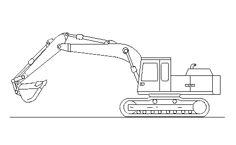
| Illustration 1 |
g00298378 |
Position the machine on level ground. Empty the bucket. Refer to Illustration 1.
- Fully extend the bucket cylinder.
- Fully retract the stick cylinder.
- Extend the stick cylinder rod 70 mm (2.8 inch) from the fully retracted position.
|
|
|
|
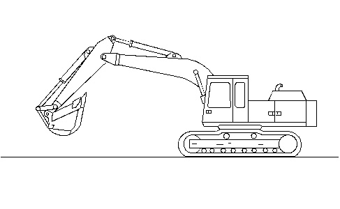
| Illustration 2 |
g01402004 |
- Raise the boom until the stick to bucket pin is the same height as the boom foot pin. Refer to Illustration 2.
- Measure each cylinder length from cylinder pin to cylinder pin.
- Stop the engine.
- Leave the machine in this position for 5 minutes. Measure each cylinder length from cylinder pin to cylinder pin for drift.
- Start the engine.
- Fully extend the bucket cylinder.
- Fully extend the stick cylinder.
- Retract the stick cylinder rod 60 mm (2.4 inch) from the fully extended position.
|
|
|
|
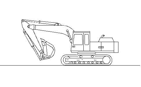
| Illustration 3 |
g01401745 |
- Raise the boom until the stick to bucket pin is 600.0 mm (23.6 inch) high from ground level. Refer to Illustration 3.
- Measure the stick cylinder length from cylinder pin to cylinder pin.
- Stop the engine.
- Leave the machine in this position for 5 minutes. Measure the stick cylinder length from cylinder pin to cylinder pin for drift.
- Start the engine.
- Fully retract the bucket cylinder.
- Fully retract the stick cylinder.
|
|
|
|
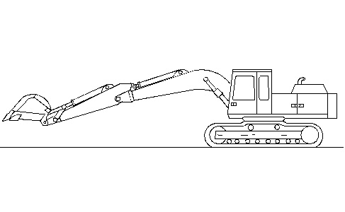
| Illustration 4 |
g01401747 |
- Raise the boom until the stick to bucket pin is 600.0 mm ( 23.6 inch) high from ground level. Refer to Illustration 4.
- Measure the bucket cylinder length from cylinder pin to cylinder pin.
- Stop the engine.
- Leave the machine in this position for 5 minutes. Measure the bucket cylinder length from cylinder pin to cylinder pin for drift.