Specification
Note: Certain machines will default to “Economy Mode” at machine startup. Change to “High Hydraulic Power Mode” before performing the test procedure.
| “Swing Speed and Swing Drift on a Slope” | ||||
|---|---|---|---|---|
| Swing Time (seconds) | ||||
| Item | New | Rebuild | Service Limit | Actual |
| Right Swing | 5.5 or less | 6.3 or less | 7.0 or less | |
| Left Swing | ||||
| Swing Drift mm (inch) | ||||
| Item | New | Rebuild | Service Limit | Actual |
| Right Swing | 0 | 0 | 0 | |
| Left Swing | ||||
Introduction
Measuring the swing speed on a slope will determine if there is a need to check the swing motor and the anti-reaction valve. Measuring the swing drift on a slope will determine if there is a need to check the swing parking brake.
Note: The engine speed and/or the machine configuration that is used during this test can affect the results of this test. Refer to Testing and Adjusting, “Engine Performance – Test (Engine Speed)” for the engine speed that was used for this test. Refer to Testing and Adjusting, “Operational Checks” for the machine configurations that were used for this test.
Note: The relief valve pressure settings must be set to the relief valve pressure specification before performing this operational check. Refer to Testing and Adjusting, “Specifications”.
Required Tools
| Required Tools | |
|---|---|
| Description | Qty |
| Measuring Tape | 1 |
| Stopwatch | 1 |
Test Procedure
Swing Speed on a Slope
|
|
|
|
|
|
| Illustration 1 | g00298078 |
- Complete the following steps in order to measure the swing speed on a slope.
- The work tool should be empty.
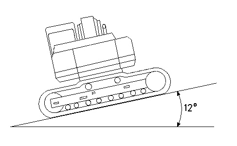
- Position the machine on a slope of 12 degrees. Refer to Illustration 1.
- Position the implements at maximum reach and close the work tool. Position the work tool above the ground so that the work tool will not come in contact with any obstacles.
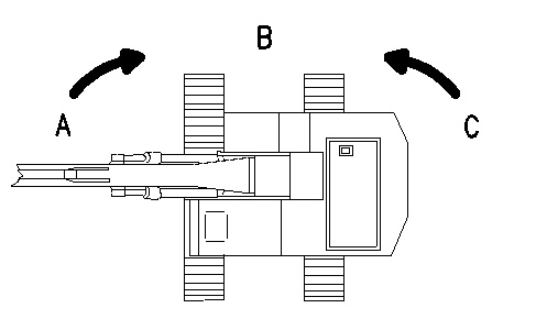
- Position the upper structure at position (A) . The upper structure should be at a 90 degree angle to the lower structure. Refer to Illustration 2.
Illustration 2 g00298079 - Measure the time that is required to swing the upper structure from position (A) to position (B) .
- Position the upper structure at position (C) . The upper structure should be at a 90 degree angle to the lower structure.
- Measure the time that is required to swing the upper structure from position (C) to position (B) .
Swing Drift on a Slope
- Complete the following steps in order to measure the swing drift on a slope.
- Position the upper structure at position (A) . The upper structure should be at a 90 degree angle to the lower structure. Refer to Illustration 3.
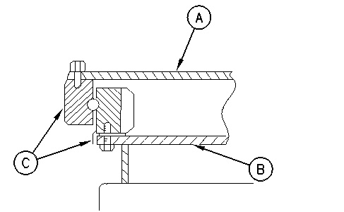
Illustration 3 g00298079 - To indicate the relationship of the two positions, put a mark (C) on the inner race and the outer race of the swing bearing. Refer to Illustration 4.
Illustration 4 g00293972 (A) Upper frame
(B) Undercarriage frame
(C) Marking
- Stop the engine.
- Leave the machine in this position for 3 minutes. Measure the swing drift on the circumference of the swing bearing.
- Start the engine.
- Position the upper structure at position (C) . The upper structure should be at a 90 degree angle to the lower structure. Refer to Illustration 3.
- Repeat Steps 1.b through 1.d.