Specification
Note: Certain machines will default to “Economy Mode” at machine startup. Change to “High Hydraulic Power Mode” before performing the test procedure.
| “Swing Speed and Overswing on Level Ground – Check” | ||||
|---|---|---|---|---|
| Overswing mm (inch) | ||||
| Item | New | Rebuild | Service Limit | Actual |
| Right Swing | 1300 mm (51.2 inch) or less | 1400 mm (55.1 inch) or less | 1600 mm (63.0 inch) or less | |
| Left Swing | ||||
| Swing Time (1) (seconds) | ||||
| Item | New | Rebuild | Service Limit | Actual |
| Right Swing | 4.9 or less | 5.4 or less | 6.0 or less | |
| Left Swing | ||||
| ( 1 ) | The time that is required to complete a 180 degree swing operation |
Introduction
Measuring the swing speed and the overswing of the machine will determine if there is a need to check the swing motor or the anti-reaction valve. The fine swing control switch (if equipped) must be in the OFF position.
Note: The engine speed and/or the machine configuration that is used during this test can affect the results of this test. Refer to Testing and Adjusting, “Engine Performance – Test (Engine Speed)” for the engine speed that was used for this test. Refer to Testing and Adjusting, “Operational Checks” for the machine configurations that were used for this test.
Note: The relief valve pressure settings must be set to the relief valve pressure specification before performing this operational check. Refer to Testing and Adjusting, “Specifications”.
Required Tools
| Required Tools | |
|---|---|
| Description | Qty |
| Measuring Tape | 1 |
| Stopwatch | 1 |
Test Procedure
|
|
|
|
|
|
| Illustration 1 | g00297618 |
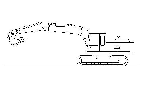
- Position the machine on level ground. Refer to Illustration 1.
Note: The bucket should be empty.
- Stop the engine.
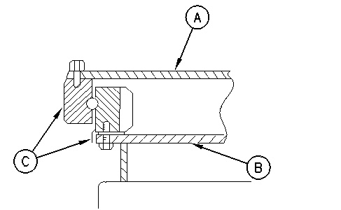
- To indicate the relationship of the two positions, put a mark (C) on the inner race and the outer race of the swing bearing. The mark will be used as a target to stop the swing operation. Refer to Illustration 2.
|
|
|
|
|
|
| Illustration 2 | g00293972 |
|
(A) Upper frame (B) Undercarriage frame (C) Marking |
|
- Start the engine.
- Move the swing joystick in either direction until the machine completes a 180 degree swing operation away from the target.
- Move the swing joystick in either direction until the machine completes a 180 degree swing operation toward the target. Return the swing joystick to the NEUTRAL position at the target.
- Measure the amount of overswing by measuring the distance between the marks on the swing bearing. Refer to Illustration 2.
Note: Use a point that is visible from the operator seat as a reference point for the target.