Specification
| “Relief Valve (Crossover) – Test and Adjust” | |||
| Machine Settings | Power Shift Pressure 3500 kPa (508 psi) |
||
| Item | Direction | Specification | Actual |
| Left Travel | Forward | 37500 + 1500 – 2000 kPa (5439 + 218 – 290 psi) | |
| Reverse | 37500 + 1500 – 2000 kPa (5439 + 218 – 290 psi) | ||
| Right Travel | Forward | 37500 + 1500 – 2000 kPa (5439 + 218 – 290 psi) | |
| Reverse | 37500 + 1500 – 2000 kPa (5439 + 218 – 290 psi) | ||
Introduction
The crossover relief valves are located on the travel counterbalance valves. The following procedure will determine if the crossover relief valves are out of adjustment.
Required Tools
|
|
|
|
|
|
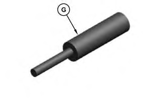
| Illustration 1 | g03406165 |
|
(G) Track Block |
|
| Required Tools | ||
|---|---|---|
| Part Number | Description | Qty |
| 8T-0861 | Pressure Gauge ( 60000 kPa (8700 psi)) |
2 |
| 8T-0856 | Pressure Gauge ( 6000 kPa (870 psi)) |
1 |
| 418-3612 | Track Block | 1 |
Machine Preparation
- Position the machine on level ground.
- Stop the engine.
- Connect a 60000 kPa (8700 psi) pressure gauge to pressure tap (1) . Use this pressure gauge to monitor the crossover relief valve pressure setting of the right travel motor.
|
|
|
|
|
|
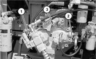
| Illustration 2 | g01266656 |
|
Pump compartment (1) Pressure tap (delivery pressure for drive pump) (2) Pressure tap (delivery pressure for idler pump) (3) Pressure tap (power shift pressure) |
|
- Connect a 60000 kPa (8700 psi) pressure gauge to pressure tap (2) . Use this pressure gauge to monitor the crossover relief valve pressure setting of the left travel motor.
- Connect a 6000 kPa (870 psi) pressure gauge to pressure tap (3) .
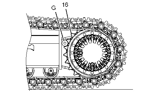
- Place track block (G) in sprocket (16) in order to block forward left travel. Refer to Illustration 3.
|
|
|
|
|
|
| Illustration 3 | g03324793 |
|
Sprocket (left track) (16) Sprocket (G) 418-3612 Track Block |
|
Test Procedure
Note: A temporary setting of the main relief valve is required before travel crossover relief valves can be tested. Refer to Testing and Adjusting, “Relief Valve (Main) – Test and Adjust”.
- Start the engine.
- Increase the hydraulic oil temperature to 55° ± 5°C (131° ± 9°F).
- Start Service Mode and input a fixed power shift pressure of 3500 kPa (508 psi).
- Press menu key (J) .
Note: If more than 30 seconds pass between pushing the keys on the keypad, the menu mode will be Canceled and the previous display will be restored to message display (A) .
- Press right key (F) in order to highlight “SERVICE” menu option.
- After the “SERVICE” option is highlighted, press OK key (I) .
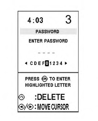
- After OK key (I) is pressed, the screen in Illustration 5 will be displayed. The password for the service menu is “FFF2”. The keys for direction are used to input the password. Press left key (D) or right key (F) in order to change the position of the flashing character. Press OK key (I) in order to enter the highlighted character.
Illustration 5 g01650914 - After entering the last letter of the password, the monitor will continue with the “SERVICE” screen.
- Repeatedly press down key (E) in order to highlight the “DEVICE TEST” line on the display.
- After the “DEVICE TEST” line is highlighted, press OK key (I) .
- Once the “DEVICE TEST” screen is displayed, press down key (E) until “POWER SHIFT PRES” appears on the display.
- When “POWER SHIFT PRES” is highlighted, press OK key (I) .
- Place the machine controls at the following settings: engine speed dial 3 and AEC switch OFF. Refer to Testing and Adjusting, “Engine Performance – Test (Engine Speed)” for engine rpm settings.
Note: Press OK key (I) within 5 seconds after completion of Step 3.j.
- The “POWER SHIFT PRES” will now be displayed. Line 4 of the display will now change to a numeric value. These characters represent the power shift pressure (kPa).
- Press left key (D) or right key (F) in order to increase or decrease the numeric value that is displayed on line 4 of the display. Pressing left key (D) decreases the power shift pressure. Pressing right key (F) increases the power shift pressure.
Note: The value for power shift pressure on the monitor may not always match the pressure reading on the pressure gauge. Adjust the value on the monitor until the desired power shift pressure is attained on the pressure gauge that is connected to the pressure tap for power shift pressure. The actual power shift pressure must be 3500 kPa (508 psi) on the pressure gauge.
Note: To prevent a change in power shift pressure during the relief valve adjustment, do not exit the “DEVICE TEST” screen and do not turn the engine start switch to the OFF position.
Note: Refer to Systems Operation, “Monitoring System” for additional information on Service Mode.
- Press menu key (J) .
|
|
|
|
|
|
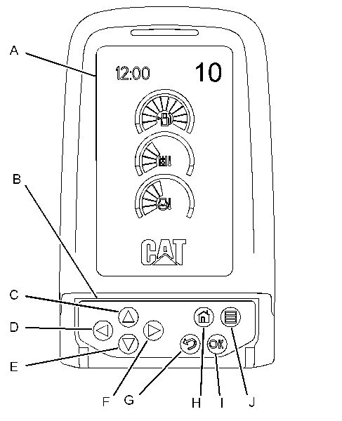
| Illustration 4 | g01321378 |
|
Monitor (A) Display (B) Keypad (C) Up key (D) Left key (E) Down key (F) Right key (G) Cancel key (H) Home key (I) OK key (J) Menu key |
|
- Slowly move the left travel control lever to full FORWARD position and check the pressure gauge reading at pressure tap (2) . The pressure setting of crossover relief valve (8) should be 37500 + 1500 – 2000 kPa (5439 + 218 – 290 psi).
|
|
|
|
|
|
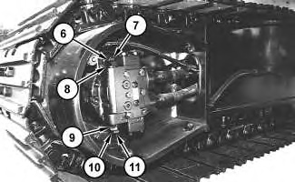
| Illustration 6 | g01622567 |
|
Travel brake valve (left side) (6) Locknut (7) Adjustment screw (8) Crossover relief valve (forward left travel) (9) Crossover relief valve (reverse left travel) (10) Locknut (11) Adjustment screw |
|
- Return the left travel control lever to the NEUTRAL position.
- In order to adjust crossover relief valve (8) , loosen locknut (6) and turn adjustment screw (7) until the pressure gauge reading at pressure tap (2) is 37500 + 1500 – 2000 kPa (5439 + 218 – 290 psi).
Note: Turn adjustment screw (7) clockwise in order to increase the pressure. Turn adjustment screw (7) counterclockwise in order to decrease the pressure.
Note: Always make final pressure adjustment on pressure rise.
- Tighten locknut (6) to a torque of 92 ± 8 N·m (68 ± 6 lb ft).
- Place track block (G) in sprocket (16) in order to block reverse left travel.
- Slowly move the left travel lever to full REVERSE position and check the pressure gauge reading at pressure tap (2) . The pressure setting of crossover relief valve (9) should be 37500 + 1500 – 2000 kPa (5439 + 218 – 290 psi).
- Return the left travel control lever to the NEUTRAL position.
- In order to adjust crossover relief valve (9) , loosen locknut (10) and turn adjustment screw (11) until the pressure gauge reading at pressure tap (2) is 37500 + 1500 – 2000 kPa (5439 + 218 – 290 psi).
Note: Turn adjustment screw (11) clockwise in order to increase the pressure. Turn adjustment screw (11) counterclockwise in order to decrease the pressure.
Note: Always make final pressure adjustment on pressure rise.
- Tighten locknut (10) to a torque of 92 ± 8 N·m (68 ± 6 lb ft).
In order to adjust the crossover relief valves on the right travel motor, place blocker pin (5) in the sprocket for right travel. Use the pressure gauge at pressure tap (1) in order to monitor the crossover relief valve pressure settings for the right travel motor. Adjust the crossover relief valves on the right travel motor in the same manner as the adjustment for the left travel motor.
- After relief valve adjustments, cancel Service Mode.
- Return the main relief valve pressure to the specified setting after crossover relief valve pressure setting is attained. Refer to Testing and Adjusting, “Relief Valve (Main) – Test and Adjust”.