Specification
| “Swing Bearing Movement – Measure” | |||
| Specification For Vertical Movement Of The Swing Bearing | |||
| Item | Specification | Actual | Average |
| New | 1.5 mm (0.06 inch) | 1. | |
| 2. | |||
| 3. | |||
| Service Limit | 3.0 mm (0.12 inch) | 1. | |
| 2. | |||
| 3. | |||
| Specification For Circular Movement Of The Swing Bearing | |||
| Item | Specification | Actual | Average |
| New | 4.5 mm (0.18 inch) | 1. | |
| 2. | |||
| 3. | |||
| 4. | |||
| Service Limit | 13.5 mm (0.53 inch) | 1. | |
| 2. | |||
| 3. | |||
| 4. | |||
Introduction
Use the procedures that follow in order to check the vertical movement and the circular movement of the swing bearing. Two dial indicators with magnetic bases are required for the procedures.
Required Tools
| Tool | Qty | Description |
| A | 2 | Dial Indicator |
Procedure To Measure Vertical Movement Of The Swing Bearing
- Place the machine on level ground.
- Empty the bucket.
- Position the upper structure parallel with the tracks.
- Inspect the static torque of the bolts in the swing bearing in order to make sure that the bolts are tightened properly.
- Set the torque wrench to a torque value of 800 N·m (590 lb ft).
- Make a mark on the head of the bolt that is relative to the carbody or the bearing race.
- Apply the specified torque to the bolt.
- If the head of the bolt does not move, the torque is within the specification.
- If the head of the bolt moves, replace the bolt.
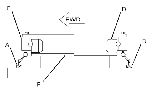
- Refer to Illustration 1. Position dial indicator (A) between the carbody and the outer race of the swing bearing (C). Position dial indicator (B) between the carbody and the outer race of the swing bearing (C) .
Note: Position the dial indicators at the front center of the carbody and at the rear center of the carbody.
|
|
|
|
|
|
| Illustration 1 | g01107785 |
|
(A) Dial indicator (B) Dial indicator (C) Outer race of the swing bearing (D) Inner race of the swing bearing (F) Carbody |
|
- Adjust both dial indicators to “zero”.
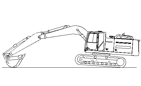
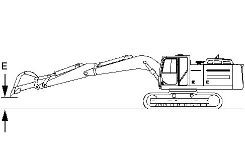
- Position the machine as shown in Illustration 3. The angle between the ground and the track should be approximately 15 degrees.
|
|
|
|
|
|
| Illustration 3 | g02173685 |
- Calculate the total distance of movement between dial indicator (A) and dial indicator (B). Record the total distance movement of in Table 1.
Note: This measurement is one of three measurements of the vertical swing bearing movement to be used in Step 14.
- Reposition the machine as shown in illustration 2.
- Note the distance movement of both of the dial indicators. Calculate the difference for each dial indicator and the measurement at the zero point that was measured in Step 7.
Note: The difference calculated for each dial indicator should be less than ± 0.05 mm (± 0.002 inch). A greater distance may indicate the dial indicator has moved out of the original zero position This greater distance also indicates that the measurement from Step 9 is not a valid measurement and additional vertical swing bearing movement measurements are necessary. Repeat Steps 6 through 11.
- Remove the dial indicators. Rotate the upper structure three times in a clockwise direction. Rotate the upper structure three times in a counterclockwise direction.
- Repeat Steps 5 through 12 three times.
- Calculate the average of the values that were recorded in Step 9. Compare this average to the service limit specifications are shown in Table 1.
Procedure To Measure Circular Movement Of The Swing Bearing
- Place the machine on level ground.
- Empty the bucket.
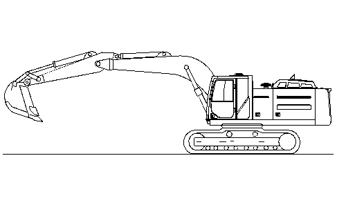
- Position the upper structure parallel to the tracks. Refer to Illustration 4 for the correct position of the boom, of the stick, and of the bucket.
|
|
|
|
|
|
| Illustration 4 | g02173688 |
|
(E) 1000 mm (39.4 inch) |
|
- Stop the engine.
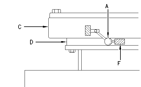
- Position dial indicator (A) on the outer race of swing bearing (C). Position a magnet (F) on the inner race of swing bearing (D). The value for the measurement will be the average of four readings.
|
|
|
|
|
|
| Illustration 5 | g00740365 |
|
(A) Dial indicator (C) Outer race of swing bearing (D) Inner race of swing bearing (F) Magnet |
|
- By hand, push the side of the bucket in order to rotate the upper structure in a counterclockwise direction as far as possible. Hold the upper structure in that position while the dial indicator is set to “zero”.
- By hand, push the side of the bucket in order to rotate the upper structure in a clockwise direction as far as possible. Record the dial indicator reading.
- Remove the dial indicator. Rotate the upper structure three times in a clockwise direction. Rotate the upper structure three times in a counterclockwise direction.
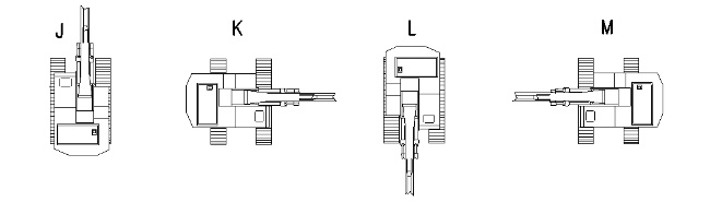
- Perform Step 5 through 8 for each machine position that is shown in Illustration 6. The evaluation of the movement of the bearing is based on the average value of the four measurements at the four positions shown in Illustration 6.
If the measurements for the circular movement of the swing bearing exceed the specifications that are listed in Table 1, check the following components for improper function, wear and/or failure:
- swing gear teeth
- pinion gear in the swing drive
- swing drive
- swing motor
- swing brake valve
- swing control valve
|
|
|
|
|
|
| Illustration 6 | g00741029 |