Specification
Note: Certain machines will default to “Economy Mode” at machine startup. Change to “High Hydraulic Power Mode” before performing the test procedure.
| “Swing Motor – Test (Measurement of Case Drain Oil)” | ||
|---|---|---|
| Machine Settings | Swing Relief Pressure | Engine Speed |
| 31400 + 1000 – 1500 kPa (4554 + 145 – 218 psi) | Speed Dial “10” AEC Switch OFF |
|
| Item | Specification (1) | Actual |
| New Swing Motor | 30 L/min (7.9 US gpm) | 1. |
| 2. | ||
| 3. | ||
| Rebuilt Swing Motor | 35 L/min (9.2 US gpm) | 1. |
| 2. | ||
| 3. | ||
| ( 1 ) | Maximum acceptable flow |
Introduction
Use the following procedure in order to measure the case drain of the swing motor.
|
|
| NOTICE |
|---|
|
Care must be taken to ensure that fluids are contained during performance of inspection, maintenance, testing, adjusting, and repair of the product. Be prepared to collect the fluid with suitable containers before opening any compartment or disassembling any component containing fluids. Refer to Special Publication, NENG2500, “Dealer Service Tool Catalog” for tools and supplies suitable to collect and contain fluids on Cat products. Dispose of all fluids according to local regulations and mandates. |
|
|
Required Tools
|
|
|
|
|
|
| Illustration 1 | g02155580 |
|
Tooling Group “D” |
|

| Tool | Item | Qty | Part Number | Description |
|---|---|---|---|---|
| D | D1 | 1 | 6V-7788 | Flow Meter
5 to 60 L/min (2 to 15 US gpm) |
| D2 | 1 | 8C-6874 | Connector | |
| D3 | 1 | 6V-9746 | O-Ring Seal | |
| D4 | 1 | 124-1901 | Permanent Coupling | |
| D5 | 3 ft | 122-6870 | Bulk Hydraulic Hose | |
| D6 | 1 | 124-2147 | Permanent Coupling | |
| D7 | 1 | 6V-8943 | Reducer | |
| D8 | 1 | 7J-9108 | O-Ring Seal | |
| D9 | 1 | 6V-8398 | O-Ring Seal | |
| D10 | 1 | 6V-8939 | O-Ring Reducer | |
| D11 | 1 | 6V-8555 | Nut | |
| F | 1 | 311-1362 | Vacuum Cap | |
Machine Preparation
- Stop the engine.
- Release the pressure in the hydraulic system. Refer to Testing and Adjusting, “Hydraulic System Pressure – Release”.
- Attach 311-1362 Vacuum Cap onto the hydraulic tank. Attach an air supply hose onto the assembly. Apply 276 to 414 kPa (40 to 60 psi). This procedure will pull a vacuum on the hydraulic system.
- Install the following tools in accordance with the flow meter tool layout. Refer to Illustration 2.
|
|
|
|
|
|
| Illustration 2 | g02155562 |
|
Flow Meter Tool Layout Tooling D (1) Case drain hose (2) Elbow (3) Swing motor (4) Swivel |
|
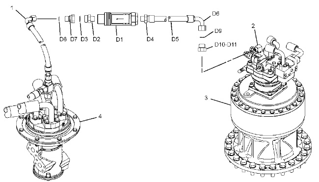
- Disconnect case drain hose (1) from elbow (2) .
- Connect the flow meter assembly (D) between elbow (2) and case drain hose (1) .
Note: Correct orientation of the flow meter is necessary. The oil flows from swing motor (3) to swivel (4) .
- Remove 311-1362 Vacuum Cap .
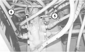
- Disconnect connector (6) from solenoid valve (5) for the swing parking brake.
|
|
|
|
|
|
| Illustration 3 | g03405937 |
|
Pilot manifold (5) Solenoid valve for swing parking brake (6) Connector |
|
Test Procedure
- Start the engine.
- Place the machine controls at the following settings: engine speed dial “10” and AEC switch OFF.
ReferenceRefer to Testing and Adjusting, “Engine Performance – Test (Engine Speed)” for engine rpm settings.
- Place the hydraulic activation control lever in the UNLOCKED position.
- Increase the hydraulic oil temperature to 55° ± 5°C (131° ± 9°F).
- Slowly move the swing joystick and make sure that the swing parking brake is activated.
- Move the swing joystick for a full SWING RIGHT. Measure the case drain oil. Refer to Table 1.
- Return the joystick to the NEUTRAL position.
- Stop the engine.
- Connect connector (6) to the solenoid valve (5) for the swing parking brake.
- Repeat this test procedure three times in order to obtain three measurements. For each test procedure, swing the upper structure to a different position.
- Connect connector (6) to the solenoid valve for the swing parking brake (5) .