Assembly Procedure
| Required Tools | |||
| Tool | Part Number | Part Description | Qty |
| A | 9S-3263 | Thread Lock Compound | 1 |
- Install the following components into ball assembly (18) : ball (19), shims (20) and spring (21) .
|
|
|
|
|
|
| Illustration 1 | g00889001 |
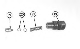
- Install ball assemblies (18) .
|
|
|
|
|
|
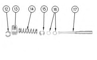
| Illustration 2 | g00889077 |

|
Improper assembly of parts that are spring loaded can cause bodily injury. To prevent possible injury, follow the established assembly procedure and wear protective equipment. |
- Tighten nut (22) to a torque of 41 ± 3 N·m (30 ± 2 lb ft). Tighten plug (23) to a torque of 41 ± 3 N·m (30 ± 2 lb ft).
- Install the following items onto spool assembly (17) : seat (13), spring (14), seat (15) and shims (16) .
|
|
|
|
|
|
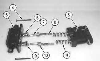
| Illustration 3 | g00888912 |
|
Improper assembly of parts that are spring loaded can cause bodily injury. To prevent possible injury, follow the established assembly procedure and wear protective equipment. |
- Press spring (14) against seat (15). Install clip (12) .
- Install the following components into housing (5) : plug (6), pushrod (7), spool assembly (8), O-ring seal (9), plunger (10) and spring (11) .
Install bolts (4) into housing (5). Tighten bolts (4) to a torque of 12 ± 1 N·m (9 ± 1 lb ft).
|
|
|
|
|
|
| Illustration 4 | g00888289 |
|
Improper assembly of parts that are spring loaded can cause bodily injury. To prevent possible injury, follow the established assembly procedure and wear protective equipment. |
- Install bolts (2). Torque bolts (2) to a torque of 30 ± 2 N·m (22 ± 1 lb ft).
|
|
|
|
|
|
| Illustration 5 | g00888262 |
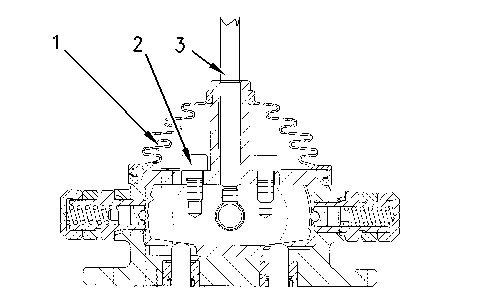
- Apply Tooling (A) to the threads of the set screw before installing. Install lever (3). Torque the set screw to a torque of 17 ± 1 N·m (13 ± 1 lb ft).
- Install boot (1) onto the valve assembly.