The engine and pump controller will monitor the machine continuously. The controller will adjust the speed of the engine and the flow of the hydraulic pump according to the machine conditions and the selections of the operator. The control system consists of the following components: engine and pump control (controller), tool electronic control, monitor panel, various switches, relays, sensors, solenoids, lamps and alarms.
The engine and pump controller communicates with the monitor panel via the CAT data link. The monitor panel will provide the following information to the operator and/or service persons: the conditions of the machine systems, diagnostic information and adjustment information. The monitor panel is also used by the operator to select operational functions.
The controller changes the output of the hydraulic pump according to the load on the machine. This process is designed to improve the rate of fuel consumption. The controller will adjust the flow of hydraulic oil to a tool according to the rate of flow that is required by the specific tool.
|
|
|
|
|
|
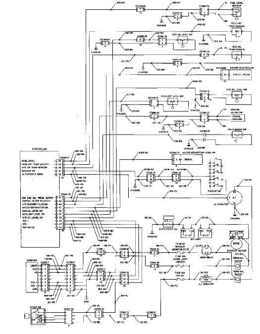
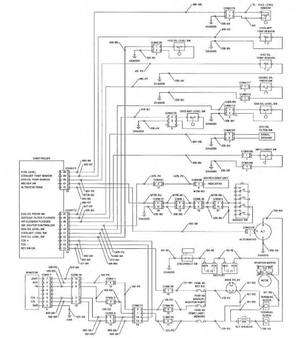
| Illustration 1 | g00775374 |
|
Schematic Of The Engine And Pump Control System ( 312C) |
|
|
|
|
|
|
|
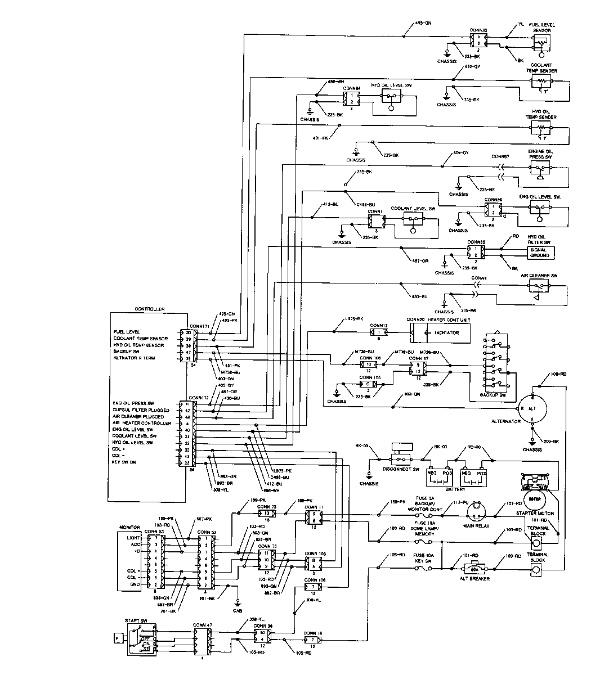
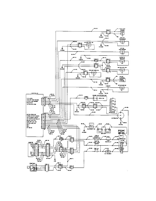
| Illustration 2 | g00775712 |
|
Schematic Of The Engine And Pump Control System 315C and 318C |
|
|
|
|
|
|
|
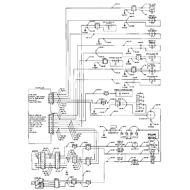
| Illustration 3 | g00686929 |
|
Schematic Of The Engine And Pump Control System For The 319C, 320C and 320C LRR |
|
|
|
|
|
|
|
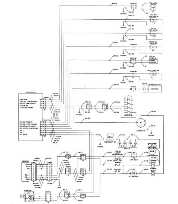
| Illustration 4 | g00986641 |
|
Schematic Of The Engine And Pump Control System of 321C |
|
|
|
|
|
|
|
| Illustration 5 | g00869851 |
|
Schematic Of The Engine and Pump Control System ( 322C) |
|
|
|
|
|
|
|
| Illustration 6 | g00907801 |
|
Schematic of the Engine and Pump Control System ( 325C and 330C) |
|