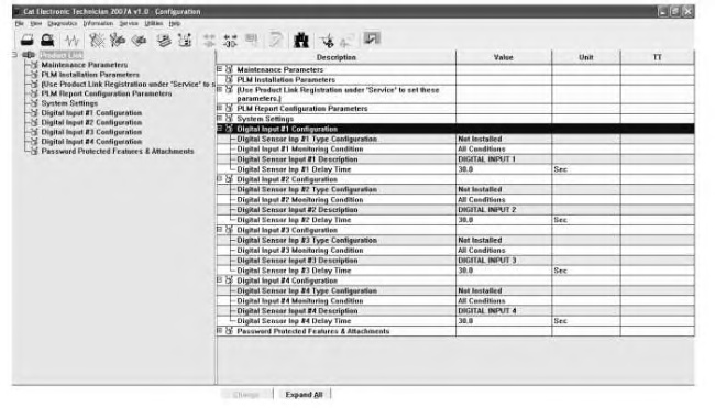
The “Digital Input Configurations” should be verified. Once verified, the “Digital Input Configurations” should be changed if required. These values are used to configure the digital sensors “#1”, “#2”, “#3”, and “#4” of the Product Link system. Refer to Systems Operation, Troubleshooting, Testing and Adjusting, “Spare Inputs” for an example of types of switches. Refer to the Systems Operation, Troubleshooting, Testing and Adjusting, “System Schematic” for an example of a wiring diagram for the inputs.
Note: The following information is applicable to all four of the digital inputs.
“Digital Input Configuration”
|
|
|
|
|
|
| Illustration 1 | g01361917 |
|
“Digital Input Configuration” Screen |
|
| Digital Input 1, 2, 3, or 4 | |||
|---|---|---|---|
| Sensor | Definition | Configuration | Notes |
| “Digital Sensor Input 1, 2, 3, or 4 Configuration Type” | The “Digital Sensor Input 1, 2, 3, or 4 Configuration Type” parameter defines whether a sensor is attached and, if attached, the state of the switch contacts under normal operating conditions (Normally Open or Normally Closed). | “Not Installed”: The user cannot set the sensor to “Not Installed”. No sensor attached to the input. The user can set the type of sensor by the following methods: “Not Configured”: Sensor may be attached to the input but not in use. “Normally Closed”: Sensor is at a closed (or low) state under normal operating conditions. “Normally Open”: Sensor is at an open (or high) state under normal operating conditions. |
The user cannot set the sensor to “Not Installed”. “Not Installed” is the factory default. |
| “Digital Input 1, 2, 3, or 4 Monitoring Condition” | Defines the monitoring condition for the digital input. If the digital input is in the alarm state (opposite the normal state) as specified in “Digital Sensor Input 1, 2, 3, or 4 Type Configuration”, for the delay time specified in “Digital Sensor Input 1, 2, 3, or 4 Delay Time”, while the “Digital Input 1, 2, 3, or 4 Monitoring Condition” is true, an event is recorded and sent to the Equipmentmanager application. | Set for the desired monitoring condition as follows: All Conditions: Will monitor input without regard to key position or engine status. Key Off/Engine Off. Will monitor the digital input when key is OFF and engine is not running. Key On/Engine OFF: Will monitor the digital input when key is ON and engine is not running. Key On/Engine On: Will monitor input when key is ON and engine is running. |
“All Conditions” is the factory default. With key Off/Engine Off, status changes will only be monitored when the PL300 wakes up for scheduled reports. An Input on these switches will not trigger the PL300 to “wake up”. |
| “Digital Sensor Input 1, 2, 3, or 4 Description” | The “Digital Sensor Input 1, 2, 3, or 4 Description” parameter is a 24 character field used to describe what the sensor is monitoring. This value is used in the office software to display the sensor status. | Enter a maximum of 24 characters for the description of the digital sensor input, for example “TRACK TENSION SENSOR”. | The default is “DIGITAL INPUT 1, 2, 3, or 4”. |
| “Digital Sensor Input 1, 2, 3, or 4 Delay Time” | Defines the delay time before an alarm condition is recorded. If the digital input is in the alarm state (opposite the normal state) as specified in “Digital Sensor Input 1, 2, 3, or 4 Type Configuration”, for the delay time specified in “Digital Sensor Input 1, 2, 3, or 4 Delay Time”, while the “Digital Input 1, 2, 3, or 4 Monitoring Condition” is true, an event is recorded and sent to the Equipmentmanager application. It is important to set this time correctly so spurious alarms are not set or alarms are missed. | Enter the delay time value for the digital sensor input in seconds. | The default value is 30.0 seconds. This value can be between 0.1 to 1200 seconds. |
“Digital Sensor Input #x Type Configuration” Parameter
|
|
|
|
|
|
| Illustration 2 | g01361927 |
|
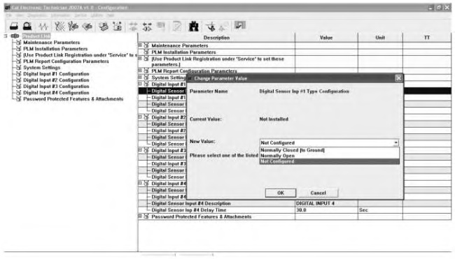
“Digital Input Type Configuration” Screen |
|
The digital sensor type configuration informs the system of how to interpret the data from the attached sensor. Refer to Systems Operation, Troubleshooting, Testing and Adjusting, “Configuration” for the following information:
- Accessing parameters
- Changing parameters
Refer to Table 1 for further information about this parameter.
“Digital Sensor Input #x Monitoring Condition” Parameter
|
|
|
|
|
|
| Illustration 3 | g01361928 |
|
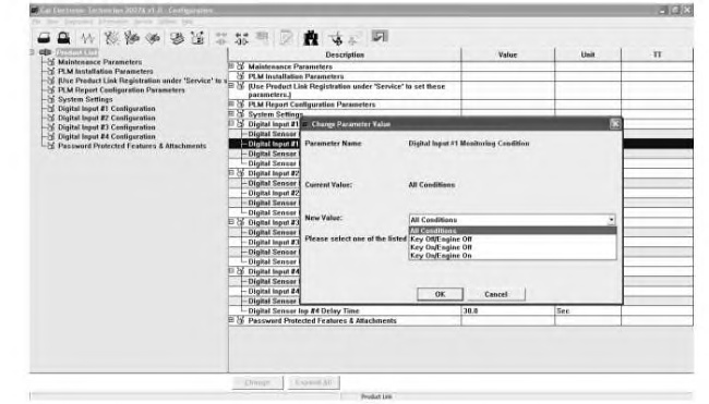
“Digital Input Monitoring Condition” Screen |
|
Refer to Table 1 for further information about this parameter.
“Digital Sensor Input #x Description” Parameter
|
|
|
|
|
|
| Illustration 4 | g01361929 |
|
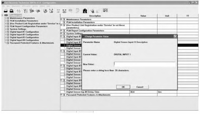
“Digital Spare Input Description” Screen |
|
Refer to Table 1 for further information about this parameter.
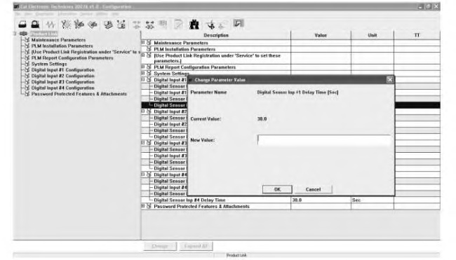
Digital Sensor Input #x Delay Time
|
|
|
|
|
|
| Illustration 5 | g01361930 |
|
“Digital Input Delay Time” Screen |
|
Refer to Table 1 for further information about this parameter.
