The “machine system” refers to the arrangement of valves and hydraulic lines on the excavator. The systems that are covered by this manual are described in Systems Operation, “General Information” for the Tool Control System. The setting of the “system” of the machine is programmed at the factory. This setting is parameter 101 under the “CONFIGURATION” menu. This setting is modified in the field under the following conditions:
- When an ECM is replaced all of the settings must be reprogrammed.
- An aftermarket tool control system and the related hardware are added to a machine.
- Hardware changes and/or hardware additions are made in order to change the function of the tool control system.
Table 1 and Table 2 list the eight different parameters that pertain to the machine control system. When the first parameter 101 is selected, the remaining seven parameters are reset automatically. The values for these settings are already stored in the memory of the ECM. These parameters are dependent upon hardware and the parameters refer to the installation status of various valves. If parameter 101 is reprogrammed and the appropriate hardware is not installed on the machine, the following scenarios may happen: or
- The tool control will not function properly.
- The tool will not function at all.
- Damage to the tool may result.
In Table 1 and Table 2, parameter 101 lists the common systems that are available. More systems may be available for selection in the menu that is displayed on the monitor. Only ONE selection from the list in the table will work properly with your machine with the specific tool control hardware that is installed.
| TOOL CONTROL SYSTEMS | ||||
|---|---|---|---|---|
| Parameter | Name | Description | ||
| 101 | “Machine System” | Option | Tool Control System | System Description |
| “NOT CONFIGURED” | ||||
| “NACD Multi-Proc” | 14 | Combined Function Auxiliary Pump Joystick with Thumb Slide Control Drain Line before Oil Cooler |
||
| 17 | Combined Function Auxiliary Pump Joystick with Thumb Slide Control Drain Line after Oil Cooler |
|||
| “NACD Hammer” | 3 | One Way Two Pump Flow Foot Switch |
||
| “NACD Thumb” | 5 | Two-Way One Pump Flow Pedal |
||
| “NACD Shear” | 11′ | Combined Function Auxiliary Control Valve ON/OFF Switch |
||
| “NACD Complete” | ||||
| “NACD Tilt BKT & Thumb” | ||||
| “COSA Hammer” | 7 | One Way One Pump Flow Electronic Control |
||
| “COSA Shear” | 9 | One-Way/Two-Way Medium Pressure Pump Electronic Control |
||
| “COSA Clamshell” | ||||
| “COSA Auxiliary Pump” | G’2 | Medium Pressure Pump Manual Control |
||
| “COSA Common” | G’1C | Combined Function Manual Control or Electronic Control |
||
| “COSA Shear ELE” | G14 | Combined Function Medium Pressure Pump Electronic Control |
||
| “COSA Small Shear” | 10 | Medium Pressure Only Electronic Control |
||
| TOOL CONTROL SYSTEMS | ||||
|---|---|---|---|---|
| Parameter | Name | Description | ||
| 101 |
“Machine System” | Option | Tool Control System | System Description |
| “SCM Auxiliary Pump” | 12 | Two-Way One Pump Flow Pedal |
||
| “SCM Common” | 2 | Combined Function Pedal |
||
| “SCM Demolition” | 2′ | Combined Function Two Pedal Control Demolition |
||
| “SCM Hammer #1” | 1 | One Way One Pump Flow Pedal |
||
| “SCM Hammer #2” | 3′ | One Way Two Pump Flow Pedal |
||
| “SCM Hammer-U” | 1′ | One Way Two Pump Flow Pedal |
||
| “SCM Shear” | 11 | Combined Function Auxiliary Control Valve Pedal |
||
| “Bucket” | No Auxiliary Function Needed. | |||
| “Special Application” | ||||
| 102 | “Attachment Controller ” “Installation Status” |
“INSTALLED” or “NOT INSTALLED” | ||
| 103 | “Proportional Reducing Valve” “Installation Status” |
“INSTALLED” or “NOT INSTALLED” | ||
| 104 | “Valve 1 ” “Installation Type” |
“INSTALLED” or “NOT INSTALLED” | ||
| 105 | “Valve 2 ” “Installation Type” |
“NOT INSTALLED” “F2-ONE WAY” “F2-TWO WAY” “F2-ONE WAY OR TWO WAY” |
||
| 106 | “Valve 3” “Installation Type” |
“NOT INSTALLED” “F3-ONE WAY” “F3-TWO WAY” “F3-ONE WAY OR TWO WAY” |
||
| 107 | “Valve 4 ” “Installation Type” |
“NOT INSTALLED” “F4-ONE WAY” “F4-TWO WAY” “F4-ONE WAY OR TWO WAY” |
||
| 108 | “Combination Valve ” “Installation Type” |
“NOT INSTALLED” “VALVE2 COMBINE” “VALVE3 COMBINE” “VALVE4 COMBINE” |
||
Programming The Machine System
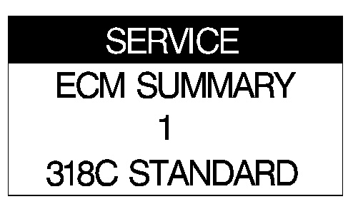
In order to program any of the parameters of the machine, you must first enter Service Mode on the monitor. This procedure is described in full in Troubleshooting, “Using Service Mode” for the Tool Control System. Immediately after entering the password for the service mode, the following screen will be on the monitor:
|
|
|
|
|
|
| Illustration 1 | g00884200 |
|
Typical example |
|
|
|
|
|
|
|
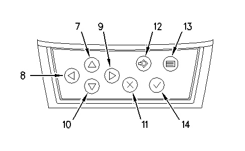
| Illustration 2 | g01006048 |
|
Monitor Panel (7) Up key (8) Left key (9) Right key (10) Down key (11) Cancel key (12) Set key (13) Menu key (14) OK key |
|
Use down key (10) in order to highlight line 2. Use right key (9) and scroll until “CONFIGURATION” is on the display. If you press right key (9) again, “TOOL PROGRAM” is on the display. Under these two headings, you will program all of the parameters of the machine. The parameters that are available for programming are shown in the following illustration:
|
|
|
|
|
|
| Illustration 3 | g01000782 |
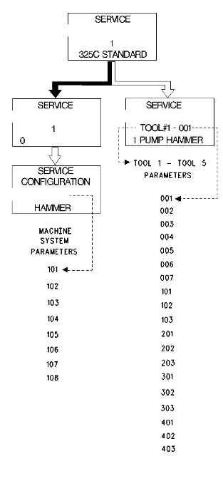
After the “CONFIGURATION” screen is reached, press down key (10) in order to highlight the third line. Use left key (8) or right key (9) in order to scroll through the eight parameters that are available. The only parameter that will normally be modified is parameter 101. When this parameter is changed, the remaining seven parameters change automatically. Press set key (12) in order to save the new value. When the value is saved, the line that is highlighted will automatically change from the fourth line to the third line.