Table 1
| Required Tools |
| Tool |
Part Number |
Part Description |
Qty |
| A |
1U-9352 |
Engine Stand |
1 |
| FT-1870 |
Adapter Assembly |
1 |
| D |
FT-1997 |
Strap |
1 |
| E |
138-7575 |
Link Bracket |
3 |
| F |
5P-0960 |
Molybdenum Grease |
1 |
| G |
5N-5561 |
Silicone Lubricant |
1 |
| H |
2S-3230 |
Bearing Lubricant |
1 |
| J |
5P-3931 |
Anti-Seize Compound |
1 |
| K |
9S-3263 |
Thread Lock Compound |
1 |
| L |
5P-3413 |
Pipe Sealant |
1 |
| M |
FT-0520 |
Adapter |
1 |
| – |
14 mm Threaded Rod (127 mm (5 inch)) |
2 |
| N |
4C-9527 |
Seal Installer |
1 |
|
| NOTICE |
|
Failure to follow the recommended procedure or the specified tooling that is required for the procedure could result in damage to components.
To avoid component damage, follow the recommended procedure using the recommended tools.
|
|
|
|
|
|
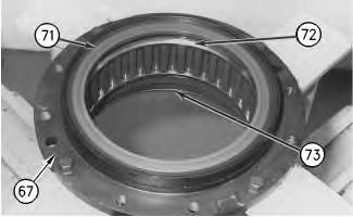
| Illustration 1 |
g00933415 |
- Fasten housing (67) to Tooling A. Install outer races (72) and (73) in the housing. Install the races evenly until the races contact the counterbores in the housing.
- Replace the O-ring seal that is used under retainer (71) with a new O-ring seal. Apply Tooling F on the O-ring seal. Install the O-ring seal in the groove in the housing. Install retainer (71) . A plastic hammer may be necessary to install the retainer.
|
|
|
|
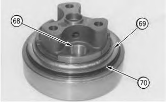
| Illustration 2 |
g00933421 |
Note: Rubber seals and all of the surfaces that contact rubber seals must be clean and dry. After the rubber seals are installed, put clean SAE 30 oil on the contact surfaces of the seals.
- Using Tooling N, install Duo-cone seal kit (70) in the spindle, as shown. Refer to Disassembly and Assembly, “Duo-Cone Conventional Seals – Install”.
- Install inner race (69) on the spindle. Install the race until the race contacts the shoulder on the spindle.
- Install three outer races (68) in the spindle. Apply clean hydraulic oil on the races.
|
|
|
|
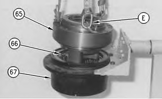
| Illustration 3 |
g00933422 |
- Apply Tooling G on balls (66) . Install balls (66) in outer race (72) .
Note: During the installation of spindle (65) in housing (67) , do not allow balls (66) to fall out of outer race (72) .
- Fasten Tooling E and a suitable lifting device to spindle (65) . Place spindle (65) in the original location in housing (67) that was marked during disassembly. Make sure that none of balls (66) fall out of the outer race during the installation of the spindle.
Note: Use Tooling D to hold the spindle and the housing together.
- Use Tooling D to fasten spindle (68) to housing (67) .
|
|
|
|
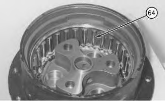
| Illustration 4 |
g00933423 |
- Rotate the spindle and the housing, as shown.
- Apply a thin coat of Tooling G on pins (64) . Install pins (64) in the housing, as shown.
|
|
|
|
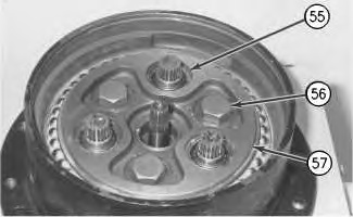
| Illustration 5 |
g00933496 |
|
|
|
|
| Illustration 6 |
g00933425 |
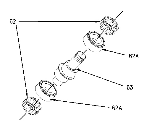
- Install bearing (62A) and roller bearing (62) on the nonsplined end of each shaft (63) . Install the shafts in the original position in gear kit (61A) that was marked during the disassembly procedure.
- Install a bearing (62A) on the splined end of each shaft (63) . Install gear kit (61) in the original position on gear kit (61A) that was marked during the disassembly procedure.
- Install roller bearing (62) on the splined end of each shaft (63) .
|
|
|
|
| Illustration 7 |
g00933436 |
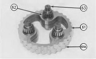
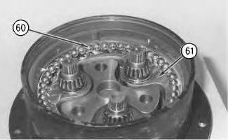
- Apply a thin coat of Tooling H on the bearings of gear kit (61) . Install gear kit (61) in the original position in the spindle that was marked during the disassembly procedure.
- Apply a thin coat of Tooling G on balls (60) . Install balls (60) in the outer race in the final drive housing, as shown.
|
|
|
|
| Illustration 8 |
g00933483 |
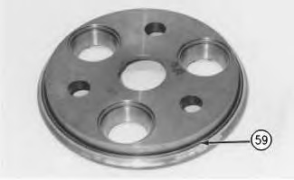
- Install inner race (59) on the plate. Install the race until the race contacts the shoulder on the plate.
|
|
|
|
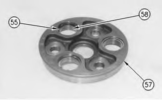
| Illustration 9 |
g00933488 |
- Install three bearing races (55) in plate (57) . Install three retaining rings (58) in plate (57) .
|
|
|
|
| Illustration 10 |
g00610690 |