Disassembly Procedure
| Required Tools | |||
|---|---|---|---|
| Tool | Part Number | Part Description | Qty |
| A | 1U-9352 | Engine Stand | 1 |
| FT-1870 | Adapter Assembly | 1 | |
| B | 1P-0074 | Slide Hammer Puller | 2 |
| C | 1U-9895 | Crossbar | 1 |
| 3H-0465 | Plate | 4 | |
| 19 mm (0.75 inch)Threaded Rod
254 mm (10 inch) Long |
2 | ||
| 8T-1757 | Nut | 4 | |
| D | FT-1997 | Strap | 1 |
| E | 138-7575 | Link Bracket | 3 |
Start By:
- Remove the final drive and the travel motor. Refer to Disassembly and Assembly, “Final Drive and Travel Motor – Remove”.
|
|
| NOTICE |
|---|
|
Care must be taken to ensure that fluids are contained during performance of inspection, maintenance, testing, adjusting, and repair of the product. Be prepared to collect the fluid with suitable containers before opening any compartment or disassembling any component containing fluids. Refer to Special Publication, NENG2500, “Dealer Service Tool Catalog” for tools and supplies suitable to collect and contain fluids on Cat products. Dispose of all fluids according to local regulations and mandates. |
|
|
|
|
| NOTICE |
|---|
|
Keep all parts clean from contaminants. Contaminants may cause rapid wear and shortened component life. |
|
|
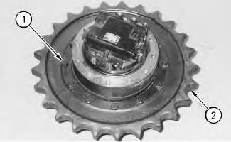
- Remove bolts (1) that hold sprocket (2) to the final drive. Use two persons to remove the sprocket from the final drive. The weight of the sprocket is approximately 23 kg (50 lb).
|
|
|
|
|
|
| Illustration 1 | g00916401 |
- Put an alignment mark across the section of the travel motor and the final drive for assembly purposes. The parts must be reinstalled in the original locations of the parts.
- Fasten the final drive and the travel motor to Tooling (A) . Make sure that the outer cover is facing upward. The weight of the final drive and the travel motor is 90 kg (200 lb).
|
|
| NOTICE |
|---|
|
Failure to follow the recommended procedure or the specified tooling that is required for the procedure could result in damage to components. To avoid component damage, follow the recommended procedure using the recommended tools. |
|
|
|
|
|
|
|
|
| Illustration 2 | g00916402 |
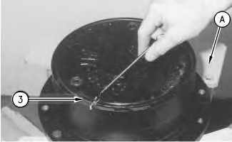
- Remove the filler plug from the cover. Use a screwdriver or use a 0.25 mm (0.010 inch) feeler gauge to a 0.38 mm (0.015 inch) feeler gauge in order to remove ring (3) from the groove between the cover and the final drive housing.
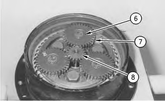
- Remove three retaining rings (6) . Remove three gears (7) . Remove the retaining ring and gear (8) .
|
|
|
|
|
|
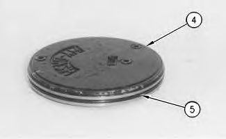
| Illustration 4 | g00916405 |
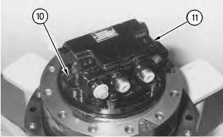
- Use the following procedure to disassemble the counterbalance valve.
- Remove bolts (10) . Remove counterbalance valve (11) .

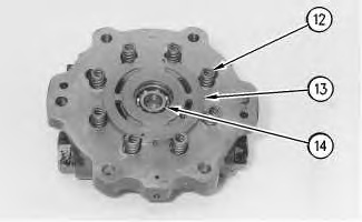
Personal injury can result from being struck by parts propelled by a released spring force.
Make sure to wear all necessary protective equipment.
Follow the recommended procedure and use all recommended tooling to release the spring force.

- Put an identification mark on port plate (13) and the cover for assembly purposes. Remove port plate (13) from the cover.
- Remove bearing (14) from the cover.
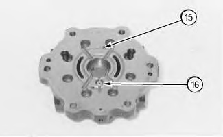
- Remove valve (16) from the cover.
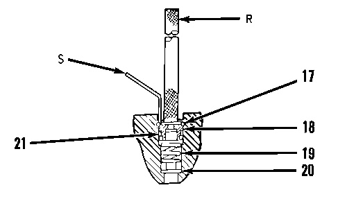
- Use a steel rod (R) of small diameter to push down on seat (18) . Sustain pressure on the seat and remove retaining ring (17) . Remove seat (18) , spring (19) , and valve (20) from the cover. Remove O-ring seal (21) from the seat.
Illustration 9 g00610440 (R) Steel Rod
(S) Seal Pick
Personal injury can result from being struck by parts propelled by a released spring force.
Make sure to wear all necessary protective equipment.
Follow the recommended procedure and use all recommended tooling to release the spring force.
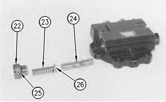
- Remove two plugs (22) , two springs (23) and two spring retainers (26) from the cover. Remove spool (24) from the cover. Remove O-ring seal (25) from each plug (22) .
Illustration 10 g00916424