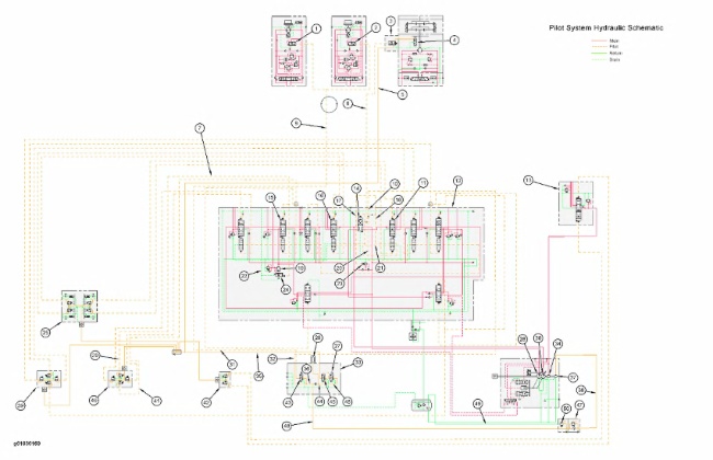
Hydraulic Schematic For Pilot Oil
|
|
|
|
|
|
| Illustration 1 | g01030169 |
|
(1) Displacement change valve (left travel) (2) Displacement change valve (right travel) (3) Control valve for swing parking brake (4) Swing parking brake (5) Line (6) Line (7) Line (9) Line (10) Line (11) Right travel control valve (12) Main control valve (13) Blade control valve (14) Straight travel valve (15) Boom I control valve (16) Left travel control valve (17) Passage (18) Passage (19) Boom drift reduction valve (20) Passage (21) Passage (22) Passage (23) Main relief valve (24) Spool (25) Pilot control valve (travel) (26) Accumulator (27) Hydraulic activation solenoid valve (28) Right pump (29) Line (30) Left pump (31) Line (32) Line (33) Pilot manifold (34) Blade pump (35) Line (36) Passage (37) Pilot pump (38) Line (39) Pilot control valve (stick and swing) (40) Pilot control valve (bucket and boom) (41) Line (42) Pilot control valve (blade) (43) Travel speed solenoid valve (44) Passage (45) Valve (46) Passage (47) Pilot filter (48) Line (49) Line (50) Pilot relief valve |
|
Pilot Oil Circuit
|
|
|
|
|
|
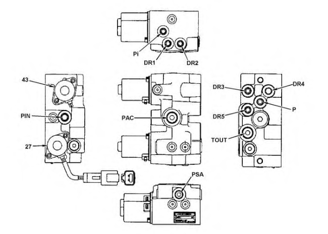
| Illustration 2 | g01032041 |
|
Ports and solenoids at the pilot manifold (27) Hydraulic activation solenoid valve (43) Travel speed solenoid valve |
|
Pilot system oil from pilot pump (37) has the following two main functions:
(1) Provide an easier operation of the control levers.
(2) Create pilot oil pressure in order to achieve various operations.
The pilot oil from pilot pump (37) goes through pilot filter (47) and line (48). The pilot oil then enters pilot oil manifold (33). The pilot oil is then separated into the following pilot circuits through respective lines (36) and (44) .
Main Control Valve
When the hydraulic activation control lever is shifted to the UNLOCKED position, hydraulic activation solenoid valve (27) is energized by an electrical signal from the limit switch within the control lever. The pilot oil then shifts valve (45) . The pilot oil flows through valve (45) and pilot line (35). The pilot oil now flows to pilot control valves (25), (39), (40) and (42) for the implements, swing and travel in order to perform machine operations. When the joysticks and/or travel levers/pedals are moved, the pilot oil flows to main control valve (12) in order to control the machine functions.
Pilot Circuit for Boom, Stick, Bucket, and Blade
The following example is given for the BOOM LOWER operation and the BOOM RAISE operation. Machine operations for a stick operation, bucket operation, travel operation and swing operation are accomplished in the same manner as the boom operation.
When the joystick for the boom is moved to the BOOM RAISE position, pilot oil from pilot control valve (40) flows through pilot line (41) to boom I control valve (15). The pilot pressure shifts the boom I control valve. The oil delivery from the left pump flows to the head end of the boom cylinders in order to perform the BOOM RAISE operation.
When the joystick for the boom is moved to the BOOM LOWER position, pilot oil from pilot control valve (40) flows through pilot line (29) to boom I control valve (15). The pilot pressure shifts the boom I control valve. The pilot oil also flows to spool (24) in order to open boom drift reduction valve (19). The return oil from the head end of the boom cylinders flows through the boom drift reduction valve and the boom I control valve to the hydraulic tank. The BOOM LOWER operation is now performed.
Note: For more information on the boom drift reduction valve, refer to Systems Operation, “Boom Hydraulic System”.
Travel Circuit
Pilot oil in passage (36) flows to passage (10) in main control valve (12) through pilot line (32). Pilot oil in passage (10) is separated into passage (18) and passage (20) .
When left travel control valve (16) or right control valve (11) is activated, oil pressure in passage (18) increases. Increased oil pressure goes to main relief valve (23) through passage (17). The increased oil pressure changes the setting of the main relief valve to the specified pressure.
Note: The main relief controls the pressure in the travel circuit. Pilot oil from passage (18) maintains the same relief setting as the other implements.
Note: For more information on travel, refer to Systems Operation, “Travel Hydraulic System”.
Straight Travel Valve Circuit
When a swing and/or implement control is operated, the pilot oil pressure in passage (20) increases. When the left travel control valve (16) or the right travel control valve (11) is operated, the increased oil pressure in passage (21) activates straight travel valve (14). This allows straight travel operation.
Note: For more information on straight travel, refer to Systems Operation, “Control Valve (Straight Travel)”.
Swing Parking Brake Release (Circuit)
When the hydraulic activation control valve is in the UNLOCKED position, oil in passage (44) will enter line (35) and line (5). The pilot oil enters the control valve for swing parking brake (3). When the implement controls and/or swing controls are operated, the pilot oil pressure in passage (20) increases. The pressure increase activates the control valve for swing parking brake (3) to the OPEN position. The pilot oil from line (5) goes through the control valve for swing parking brake (3) to swing parking brake (4). This releases the swing parking brake.
Note: For more information, refer to Systems Operation, “Swing Hydraulic System”.
Automatic Travel Speed Change Valve
Pilot oil flows from passage (36) to travel speed solenoid valve (43). When the switch for the travel speed is placed in the HIGH SPEED position, travel speed solenoid valve (43) opens. Pilot oil from passage (36) goes through travel speed solenoid valve (43). From the travel speed solenoid valve, oil enters line (31) and passes to left and right travel displacement change valves (1) and (2). Valves (1) and (2) activate and the machine travels in an optimum speed.
Note: For more information, refer to Systems Operation, “Travel Hydraulic System”.
The system pressure in the pilot circuit is limited by pilot relief valve (50), which is built into pilot filter (47) .