|
|
|
|
|
|
| Illustration 1 | g00864948 |
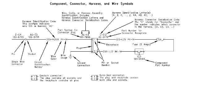
The information that follows can also be found on the Electrical System Schematic. The complete identification of harnesses and wires are shown in Illustration 1. The partial electrical schematics in this manual use abbreviated forms of harness and wire identification. Examples of the abbreviated forms are shown in Illustrations 2 and 3.
General Views and Area Views
The schematic contains line drawings of the entire machine (general views). The general views include the side view and the top view of the machine. Component locations and connector locations are shown on the general view. The schematic also contains line drawings of machine areas (area views). The area views show components and connectors that are close together.
Component Locations and Connector Locations
|
|
|
|
|
|
| Illustration 2 | g00848937 |
|
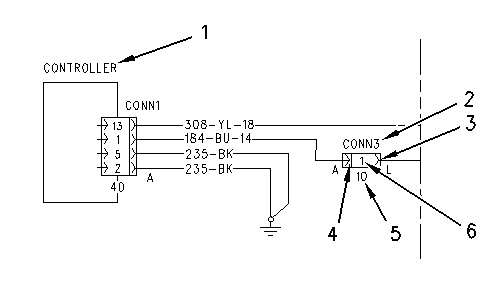
Example of a Partial Electrical Schematic (1) Component description (2) Connector number (3) Socket (Female connector) (4) Pin (Male connector) (5) Total number of Pins or Sockets on the connector (6) Pin or Socket number |
|
The component locations are identified by numbers in white circles. The white circles are used in the general views and in the area views. Components (1) are shown in the Electrical Circuit Diagram and the components are listed on the component location chart. Area views are described at the bottom of the chart.
The connector locations are identified by numbers in white circles. The white circles are used in the general views and in the area views. Connectors (2) are shown in the Electrical Circuit Diagram and the connectors are listed on the connector location chart.
Harness Identification
|
|
|
|
|
|
| Illustration 3 | g00861170 |
|
Example of a Partial Electrical Schematic (7) Wire identification (8) Harness identification |
|
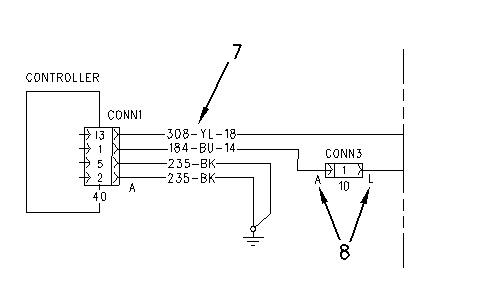
Harnesses (8) are identified by capital letters such as “A”, “L”, or “EE”. The harnesses are shown in the Electrical Circuit Diagram.
Wire Identification
Wires (7) are identified by circuit numbers, by colors, and by sizes. The wires are shown in the Electrical Circuit Diagram and the wires are listed in the wire location chart.
For example, a wire might be listed as 308-YL-18. “308” is the circuit number (wire number). “YL” is the wire color. “18” is the wire size.
The circuit numbers (wire numbers) that are on the wire location chart are sorted by the circuit function. For example, the wires “200” through “299” are ground circuits, and the wires “300” through “399” are basic machine circuits.
The wire sizes are listed by American Wire Gauge (AWG).
The abbreviations of the wire colors are shown in the following table:
| Symbol | Color |
| BK | Black |
| BU | Blue |
| BR | Brown |
| GY | Gray |
| GN | Green |
| OR | Orange |
| PK | Pink |
| PU | Purple |
| RD | Red |
| WH | White |
| YL | Yellow |