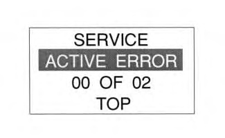
The active error mode will be displayed on the monitor panel. The active error codes correspond to an abnormal condition that is detected by the controller.
|
|

|
|
| Illustration 1 |
g00687896 |
- Enter the service mode. Select the “ACTIVE ERROR” option on the second line by using the keys for direction.
|
|

|
|
| Illustration 2 |
g00687943 |
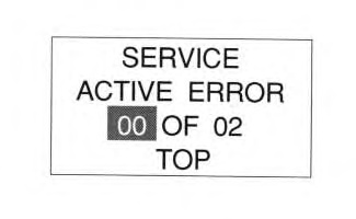
- The area that is highlighted in the illustration is showing the number of the error out of the total number of errors that are present.
|
|

|
|
| Illustration 3 |
g00687952 |
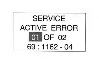
- The left arrow key and the right arrow key is used to display the error codes that are active. These keys are used to scroll through the codes. The illustration above shows the “MID-CID-FMI”. The “69” is the MID. The “1162” is the CID and the “04” is the FMI. The arrow keys are used to scroll through the active diagnostic codes.
Table 1
| Module Identification (MID) |
| Number For The Module |
Module |
| 69 |
Engine and Pump Controller |
| 6A |
Tool Controller |
| 1E |
Monitoring System |
24
(Not in 321C) |
Engine ECM |
Table 2
| Component Identifier (CID) |
| CID Number |
Name Of Component |
91
(Not in 321C) |
Throttle position signal |
| 96 |
Fuel level sensor |
| 110 |
Engine coolant temperature sensor |
| 167 |
Alternator |
| 168 |
Voltage of the power supply (keyswitch) |
| 190 |
Speed sensor |
248
( 319C, 320C, 322C, 325C, and 330C ONLY) |
Cat data link |
254
( 312C, 315C, and 321C ONLY) |
Electronic Control Module (ECM) |
271
( 312C, 315C, and 321C ONLY) |
Action Alarm |
286
(Not in 321C) |
Signal for low engine oil pressure |
| 374 |
Swing brake solenoid |
| 376 |
Travel alarm |
| 581 |
Proportional reducing valve for the power shift pressure |
| 586 |
Engine speed dial |
| 587 |
Feedback sensor for the governor actuator |
588
( 312C, 315C, and 321C ONLY) |
Communication problem between controller and monitor |
| 590 |
Engine controller |
| 598 |
Travel speed solenoid |
| 600 |
Hydraulic oil temperature sensor |
| 1161 |
Pump delivery pressure |
| 1162 |
Pump delivery pressure |
| 1525 |
Straight travel solenoid |
2002
( 319C, 320C, 322C, 325C, and 330C ONLY) |
Action alarm |
Table 3
| Failure Mode Identifier |
| FMI |
Description |
| 00 |
Above Normal Data is valid but above normal. |
| 01 |
Below Normal Data is valid but below normal. |
| 02 |
Incorrect Signal Data is erratic, intermittent, or incorrect. |
| 03 |
Voltage Above Normal |
| 04 |
Voltage Below Normal |
| 05 |
Current Below Normal |
| 06 |
Current Above Normal |
| 07 |
Improper Mechanical Response |
| 08 |
Abnormal Signal |
| 09 |
Abnormal Update |
| 10 |
Abnormal Rate of Change |
| 11 |
Failure Mode Identifier |
| 12 |
Failed Component |
| 13 |
Out of Calibration |
The MID is the code for the control module. The CID is the code for the component identification. The FMI is the failure mode identifier.


