|
|
|
|
|
|
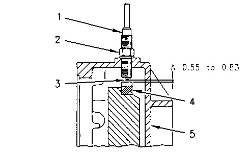
| Illustration 1 | g00667337 |
|
Installation of the speed sensor (1) Speed Sensor (2) Locknut (3) Magnetic Core (4) Gear (5) Flywheel Housing |
|
Prior to replacement of the sensor, ensure that the sensor has failed. Always check that the power is available to the sensor. Measure the voltage between the contacts of the sensor. Check for metal shavings on the magnetic tip or the gear teeth.
Perform the following procedure in order to replace the speed sensor.
- Turn the key start switch and the disconnect switch to the OFF position.
- Slowly tighten speed sensor (1) into flywheel housing (5) until magnetic core (3) contacts gear (4) .
- Turn speed sensor (1) counterclockwise. The turn should be approximately 3/4 of a rotation.
Note: For 321C make a 4/5 – 1 of a rotation.
- Temporarily tighten locknut (2) .
- Set the engine speed dial at position 1 (LOW IDLE position).
- Turn the disconnect switch to the ON position.
- Start the engine.
- Activate the service mode.
- Enter service code 11 in order to display the engine speed.
- Verify that 800 RPM is displayed.
Note: For 321C 1000 RPM.
- If the correct rpm is not displayed, turn speed sensor (1) clockwise. The turn should not be greater than 1/3 of a rotation.
- Stop the engine.
- Tighten locknut (2) to a torque of 25 N·m (18.4 lb ft).
Note: For 321C 29.5 ± 5 N·m (21 ± 4 lb ft)
- Verify that the sensor corrects the problem.
- Clear the error log. Refer to Testing and Adjusting, “Using Service Mode”.