The switch status mode is used to display the “ON” status or “OFF” status of various switches in the machine.
|
|
|
|
|
|
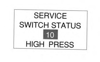
| Illustration 1 | g00687441 |
- Enter the service mode. Scroll to the above display. Use the keys for direction.
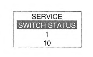
- The above illustration shows the “ID” status of the switch and the respective “ID” numbers. The following table should be used to identify the switch and the display. Highlight the third line. Use the directional keys in order to change the “ID”. The example above shows the pressure switch for the joystick in the ON position.
Table 1 Status Of The Switch ID Switch Display 1 Position of the engine speed dial “1-10” 2
(If Equipped)Air heater relay
HEATING during preheating, OFF during NO preheating“HEATING/OFF” 3
( 318C, 319C, 320C, 321C, 322C, 325C, 330C)Fine swing switch
Fine in switch ON, OFF in switch OFF“FINE/OFF” 4
( 322C ONLY)Cranking signal input
ON when cranking, OFF in switch OFF position.ON/OFF 5
Not in 321CQuick coupler switch
ON in switch ON position
OFF in switch OFF positionON/OFF 6 One-touch low idle switch
ON when pressed, OFF when not pressed“ON/OFF” 7 AEC mode switch
ON when pressed, OFF when not pressed“ON/OFF” 8 Travel mode switch
ON when pressed, OFF when not pressed“ON/OFF” 9 Travel alarm cancel switch
ON when pressed, OFF when not pressed“ON/OFF” 10 Pressure switch for the joystick
HIGH PRESS when pressure is generated in the switch circuit. LOW PRESS when pressure is not available“HIGH PRESS/LOW PRESS” 11
( 312C and 315C have only one pressure switch)Travel pressure switch (left)
HIGH PRESS when pressure is generated in the switch circuit. LOW PRESS when pressure is not available.“HIGH PRESS/LOW PRESS” 12
( 319C, 320C, 320C LRR,
318C, 321C, 325C, 330C)Travel pressure switch (right)
HIGH PRESS when pressure is generated in the switch circuit. LOW PRESS when pressure is not available.“HIGH PRESS/LOW PRESS” 13 Engine oil level switch
NORMAL when oil level is setting level or higher. LOW LEVEL when the oil level is lower than the setting level.“NORMAL/LOW LEVEL” 14 Coolant level switch
NORMAL when the coolant level is setting level or higher.“NORMAL/LOW LEVEL” 15 Hydraulic oil level switch
NORMAL when hydraulic oil level is setting level or higher. LOW LEVEL when hydraulic oil level is lower than the setting level.“NORMAL/LOW LEVEL” 16 Engine oil pressure switch
HIGH PRESS during engine running. LOW PRESS during a engine stop.“HIGH PRESS/LOW PRESS” 17 Return filter switch is clogged
PLUGGED when clogged. NORMAL when normal.“NORMAL/CLOGGED” 18 Air heater controller
HEATING during preheating. OFF during no preheating.“HEATING/OFF” 19 Automatic greasing failure.
DISABLED for non equipped machine. In equipped machine, NORMAL in normal condition. FAULT when failed.“NOT DISABLED/NORMAL/FAULT” 20 Overload switch cancel switch
ON when pushed. OFF when not pushed.“ALARM CANCEL/OFF” 21
( 312C and 315C ONLY)Implement pressure switch
HIGH PRESS when pressure is generated in switch circuit.
LOW PRESS when pressure is not available.HIGH PRESS/LOW PRESS 24
Aux. toolATT stem 1 activation status ON when operation status of attachment system is ON. OFF when status is OFF. “ON/OFF” 25
Aux. toolATT stem 2 activation status ON when operation status of attachment system is ON. OFF when status is OFF. “ON/OFF” 26
Aux. toolATT stem 3 activation status ON when operation status of attachment system is ON. OFF when status is OFF. “ON/OFF” 27
Aux. toolATT stem 4 activation status ON when operation status of attachment system is ON. OFF when status is OFF. “ON/OFF” 28 Water separator
Draining demand
DISABLED for non-equipped machine. An equipped machine, NORMAL in normal condition. FAULT in draining demand.“NOT DISABLED/NORMAL/FAULT” 29 Air cleaner
Air cleaner switch is PLUGGED when clogged. NORMAL when normal“NORMAL/PLUGGED” 30 First fuel filter
First fuel filter switch is clogged
DISABLED for non-equipped machines. Equipped machines NORMAL when normal. PLUGGED when clogged.“DISABLED/NORMAL/PLUGGED” 31 Second fuel filter
Second fuel filter switch
DISABLED for non-equipped machines. NORMAL when normal.
PLUGGED when clogged.“DISABLED/NORMAL/PLUGGED” 32 Special filter switch
DISABLED for non-equipped machines. NORMAL for normal conditions. PLUGGED when clogged.“DISABLED/NORMAL/PLUGGED” 33
( 319C, 320C, 320C LRR, 322C, 325C,
318C, 321C
330C)Pressure switch for straight travel
HIGH PRESS when pressure is generated in switch circuit. LOW PRESS when the pressure is not available.“HIGH PRESS/LOW PRESS”
|
|
|
|
|
|
| Illustration 2 | g00687447 |