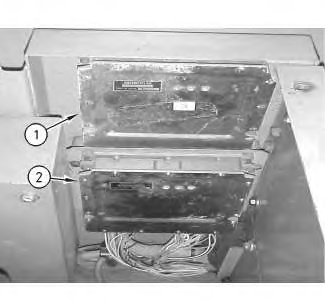
The implement ECM is attached to machines that are equipped with a System 14 or a System 17. The implement ECM is used in order to control the function of the work tool. The implement ECM is connected to the machine through two “54 pin” connectors.
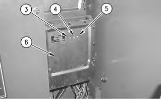
Note: The machine ECM is present on all excavators that are covered by this manual. The machine ECM controls the work tools on all tool control systems except the System 14 and the System 17. The machine ECM is also connected to the machine through two “54 pin” connectors. Both the implement ECM and the machine ECM will monitor the system through the inputs and each ECM will make adjustments to the system through the outputs. Both the implement ECM and the machine ECM are equipped with LED indicators that provide the status of the following items: power, communications and malfunction of the controller. The explanation of the flashing LED indicator is listed in table 2 and table 3.
|
|
|
|
|
|
| Illustration 1 | g00788553 |
|
The photograph shows the electronic controllers. (1) Machine ECM (2) Implement ECM |
|
|
|
|
|
|
|
| Illustration 2 | g00709793 |
|
Implement ECM (3) Green LED (4) Yellow LED (5) Red LED (6) Implement ECM |
|
| Normal LED Status | ||||
| Key Start Switch | Green LED | Yellow LED | Red LED | Remarks |
| ON | ON | OFF | OFF | The red LED will momentarily illuminate when the key start switch is turned from the OFF position to the ON position. |
| OFF | OFF | OFF | OFF | The green LED will remain illuminated for approximately 10 seconds after the key start switch is turned to the OFF position. |
| Abnormal LED Status | |
| LED Display | Description and Action |
| No LED is illuminated. | Power is not supplied to the ECM. Refer to Testing and Adjusting, “No Power Supply to Controller – Troubleshoot” for the Engine and Pump Control System. |
| The yellow LED is illuminated. | Communications between the ECM and the monitor have malfunctioned. Refer to Testing and Adjusting, “Communication Problem Between Controller and Monitor – Troubleshoot (“CID 248” and “CID 588″)” for the Engine and Pump Control System. |
| The red LED is flashing or illuminated. | The controller has malfunctioned. Replace the controller. Refer to Testing and Adjusting, “Electronic Control Module (ECM) – Replace” for the Tool Control System. |

