Switch (Clockwise Rotation)
|
|
|
|
|
|
| Illustration 1 | g00938200 |
|
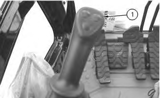
(1) Switch for work tool (clockwise rotation) |
|
|
|
|
|
|
|
| Illustration 2 | g00938239 |
|
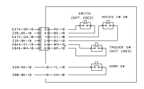
Switch for work tool (clockwise rotation) |
|
The switch for clockwise rotation of the work tool is located on the left joystick. When the switch (button) on the joystick is pressed, a signal is sent to the relay for medium pressure (clockwise rotation). The relay sends power to the solenoid for medium pressure (clockwise rotation). The work tool will rotate in a clockwise direction. The switch is not serviceable. The joystick is serviceable. This switch functions only on machines that are equipped with a System 11.
|
|
|
|
|
|
| Illustration 3 | g00991450 |
|
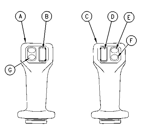
Joysticks for the System 14 and the System 17 (A) Left joystick (B) Left joystick slide control for the rotate circuit on Tool 2 and Tool 4 (C) Right joystick (D) Right joystick slide control for two-way flow on tools 2, 4, and 5 (E) Switch for one-way flow on Tool 1 (F) One touch low idle (G) Horn |
|
|
|
|
|
|
|
| Illustration 4 | g00991506 |
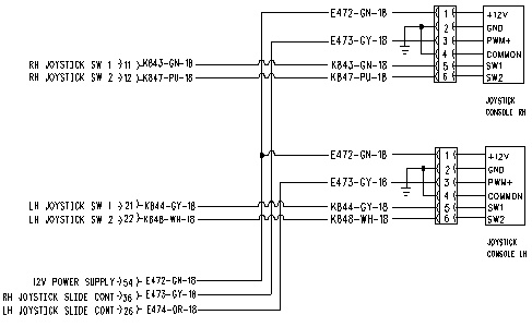
Machines that are equipped with a System 14 or a System 17 use a joystick that is equipped with a slide control switch. The left joystick slide control is used to activate the medium pressure (rotate circuit). When the left joystick slide control is moved FORWARD, a signal is sent from the Implement ECM to the extend solenoid valve on the auxiliary control valve (medium pressure). The work tool will rotate clockwise. The switch is not serviceable. The joystick is serviceable.
Switch (Counterclockwise Rotation)
|
|
|
|
|
|
| Illustration 5 | g00938202 |
|
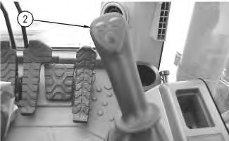
(2) Switch (counterclockwise rotation) |
|
|
|
|
|
|
|
| Illustration 6 | g00938241 |
|
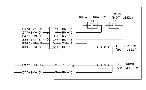
Schematic switch (counterclockwise rotation) |
|
The switch for counterclockwise rotation of the work tool is located on the right joystick. When the switch (button) on the joystick is pressed, a signal is sent to the relay for medium pressure (counterclockwise rotation). The relay sends power to the solenoid for medium pressure (counterclockwise rotation). The work tool will rotate in a counterclockwise direction. The switch is not serviceable. The joystick is serviceable. This switch functions only on machines that are equipped with a System 11.
|
|
|
|
|
|
| Illustration 7 | g00991450 |
|
Joysticks for the System 14 and the System 17 (A) Left joystick (B) Left joystick slide control for the rotate circuit on Tool 2 and Tool 4 (C) Right joystick (D) Right joystick slide control for two-way flow on Tools 2, 4, and 5 (E) Switch for one-way flow on Tool 1 (F) One touch low idle (G) Horn |
|
|
|
|
|
|
|
| Illustration 8 | g00991506 |
Machines that are equipped with a System 14 or a System 17 use a joystick that is equipped with a slide control switch. The left joystick slide control is used to activate the medium pressure (rotate circuit). When the left joystick slide control is moved BACKWARD, a signal is sent from the Implement ECM to the retract solenoid valve on the auxiliary control valve (medium pressure). The work tool will rotate counterclockwise. The switch is not serviceable. The joystick is serviceable.
Pressure Switch (Implement)
|
|
|
|
|
|
| Illustration 9 | g00775885 |
|
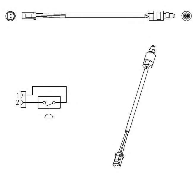
Pressure Switch (Implement) |
|
The pressure switch (implement) sends a signal to the ECM at CONN172-17. This signal tells the ECM that the implement is operating.
Pressure Switches
|
|
|
|
|
|
| Illustration 10 | g00776058 |
|
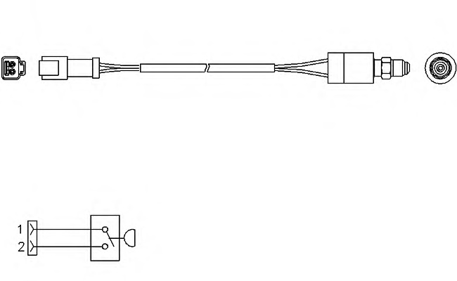
Work tool pressure switch Joystick pressure switch Medium pressure switch |
|
The three pressure switches are identical. Each of the three pressure switches tell the ECM that a specific portion of the hydraulic circuit is operating. The ECM will determine the parameters to use in order to control the hydraulic output.
The work tool pressure switch sends a signal to the ECM at CONN172-28. This switch senses an increase in pressure when the foot pedal for the work tool is pressed.
The joystick pressure switch sends a signal to the ECM at CONN172-29. This switch senses an increase in pressure when the joysticks that control the implements are operated.
The medium line pressure switch sends a signal to the ECM at CONN172-45. This switch senses an increase in pressure in the pilot line.
