The following service tools should be used in order to troubleshoot the electrical system easily:
- 6V-7070 Digital Multimeter (Heavy Duty)
- 8T-3224 Needle Tip (Multimeter)
- 7X-1710 Multimeter Probe
- 8T-8726 Adapter Cable (Three-Pin Breakout)
- 4C-4892 ORFS Fittings Group
- 6V-3000 Connector Repair Kit (Sure Seal)
- 4C-3406 Connector Repair Kit (Deutsch)
|
|
|
|
|
|
| Illustration 1 | g00241203 |
|
Digital Multimeter |
|
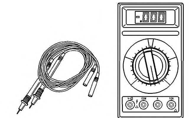
Use the 6V-7070 Digital Multimeter (Heavy Duty) or use an equivalent multimeter in order to make continuity checks and voltage measurements. For instructions on the use of the 6V-7070 Digital Multimeter (Heavy Duty), see Special Instruction, SEHS7734. The 7X-1710 Multimeter Probe is used to perform measurements at connectors without the need to disconnect the connector. The probes are pushed into the back side of the connector and alongside the wire. The 8T-8726 Adapter Cable (Three-Pin Breakout)is used to perform measurements in the circuits for the sensors.
Note: Unless you are testing a harness, the 8T-0500 Continuity Test Light or the 5P-7277 Voltage Tester is not recommended for use on electrical circuits.
Using Caterpillar Electronic Technician
|
|
|
|
|
|
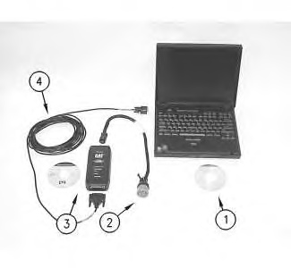
| Illustration 2 | g00719115 |
|
Connections for the Communication Adapter II and the Electronic Technician (ET) The components that are needed in order to use the Communication Adapter II and the CAT Electronic Technician in order to determine diagnostic codes are listed: (1) Current version of Caterpillar Electronic Technician software and an IBM-COMPATIBLE personal computer (2) Service diagnostic cable. (3) 171-4400 Communication Adapter II and software Special Publication, NEHS0758, “Communications Adapter II User’s Manual Contains Software” (4) Cable |
|
|
|
|
|
|
|
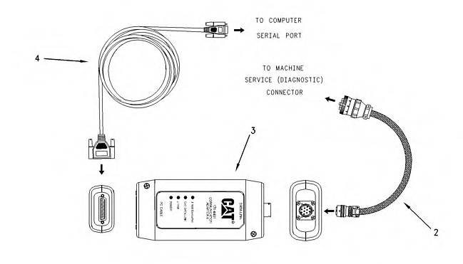
| Illustration 3 | g00738951 |
|
Connections for the Communication Adapter II and the Electronic Technician (ET) (2) cable assembly (machine control to the Communication Adapter II) (3) 171-4400 Communication Adapter II Group (4) cable assembly (serial cable to DB-9 connector) |
|
Note: Caterpillar Electronic Technician (ET) is a software program that can be used on an IBM compatible personal computer.
In order to use the Caterpillar Electronic Technician (ET), order the following materials: Special Publication, JERD2124, “ET Single Use Program License”, Special Publication, JEHP1026, “Information and Requirements Sheet”, 7X-1425 Data Link Cable and the Data Subscription and Special Publication, JERD2142, “Data Subscription”. The Special Publication, JEHP1026, “Information and Requirements Sheet” lists the required hardware and the features of the ET.
The Electronic Technician (ET) is not required in order to determine the diagnostic codes and the ET is not required in order to clear the diagnostic codes. The process of determining the diagnostic codes is easier and faster with the use of ET. The ET can also display information on the history of a diagnostic code and the parameter status of diagnostic codes. These features allow the ET to be a useful tool for troubleshooting.
The Electronic Technician connects to the machine’s diagnostic connector. The Electronic Technician communicates with the electronic control modules over the data link. The diagnostic connector is located by the fuse panel. For more information and the locations of the connectors, see Troubleshooting, “Electrical Components and Connector Locations” and the Electrical System Schematic in your machine’s Service Manual.
Connect the ET to the machine. Turn the key start switch to the RUN position. Start the ET. The ET will initiate communications with the electronic control modules on the machine. The ET will list the available electronic control modules on the machine after communication has been established.
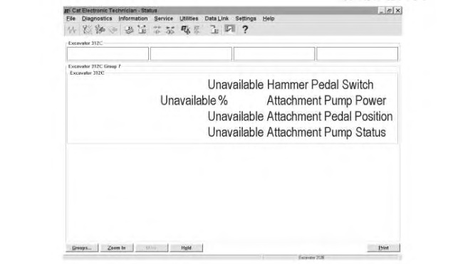
Machine Control Status Groups For The Electronic Technician
The Electronic Technician uses status groups in order to display information about the status of the parameters. There are seven machine control status groups. Status group 7 pertains specifically to the Tool Control.
|
|
|
|
|
|
| Illustration 4 | g00796788 |
|
Typical Status Group 7 for the parameters of the tool control system |
|