Since the pressure specifications, the flow rate, and engine rpm may vary with types and/or suppliers of a work tool, it is very important to follow the specifications of the supplier. Failure to follow the specifications of the supplier could result in poor performance of the work tool.
| TOOL CHART FOR FLOW TEST | ||||
| Item Number | Part Number | Part Description | Quantity | |
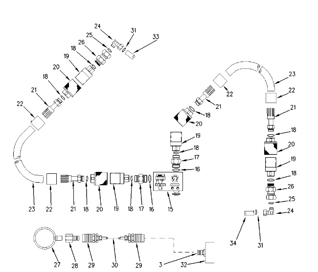
| 15 | 4C-9910 | Flow Meter | 1 | |
| 16 | 6K-6307 | O-ring seal | 2 | |
| 17 | 8C-9026 | Adapter | 2 | |
| 18 | 7M-8485 | O-ring seal | 8 | |
| 19 | 4C-6482 | Nipple | 4 | |
| 9U-5086 | Optional Dust Cap | 4 | ||
| 20 | 4C-6481 | Coupler | 4 | |
| 9U-5084 | Optional Dust Plug | 4 | ||
| 21 | 4C-8767 | Coupling | 4 | |
| 22 | 5P-1010 | Sleeve | 4 | |
| 23 | 5P-0201 | XT-5 Hose 3.5 m (12 ft) |
2 | |
| 24 | 8C-8762 | Elbow | 2 | |
| 25 | 6V-9746 | O-Ring Seal | 2 | |
| 26 | 4I-6140 | Coupling | 2 | |
| 27 | 8T-0861 | Pressure Gauge | 1 | |
| 28 | 6V-3989 | Nipple | 1 | |
| 29 | 6V-4143 | Coupler | 2 | |
| 30 | 6V-3014 | Hose | 1 | |
| 31 | 6V-8398 | O-Ring Seal | 2 | |
|
|
|
|
|
|
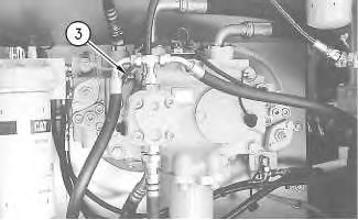
| Illustration 1 | g00993605 |
|
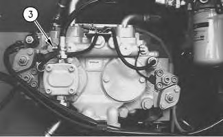
(3) Pressure tap (32) Main pump (33) Line for rotator (34) Line for rotator |
|
|
|
|
|
|
|
| Illustration 2 | g00993625 |
|
(15) Flow meter (33) Line for rotator (34) Line for rotator (35) Multitach (36) Load valve on the flow meter |
|
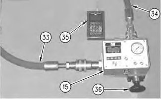
- While the engine is off, install the line for rotator (33) to the input port of flow meter (15) .
- Install the line for rotator (34) to the output port of flow meter (15) .
- Attach pressure gauge (27) to pressure tap (3) .
Note: Refer to Illustration 3 for the 320C and the 322C machines.
Note: Refer to Illustration 4 for the 325C machines.
|
|
|
|
|
|
| Illustration 3 | g01002013 |
|
Pump compartment for the 320C and the 322C (3) Pressure tap (drive pump) |
|
|
|
|
|
|
|
| Illustration 4 | g01002014 |
|
Pump compartment for the 320C and the 322C (3) Pressure tap (drive pump) |
|
- Be sure that the load valve on the flow meter (36) is in the FULLY OPEN position.
- Turn the battery disconnect switch to the ON position.
- Turn the engine start switch to the ON position. The default display screen will show on message display (6) .
|
|
|
|
|
|
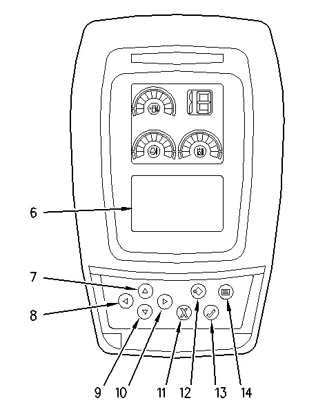
| Illustration 5 | g00993582 |
|
(6) Message display (7) Up key (8) Left key (9) Down key (10) Right key (11) Cancel key (12) Set key (13) OK key (14) Menu key |
|
|
|
|
|
|
|
| Illustration 6 | g00986293 |
|
This is a typical example of the default display screen. |
|
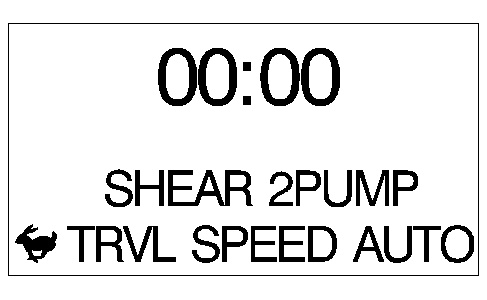
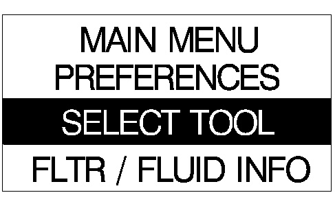
- Press menu key (14) in order to change from the default display screen to the main menu display.
|
|
|
|
|
|
| Illustration 7 | g00789231 |
|
Main menu display |
|
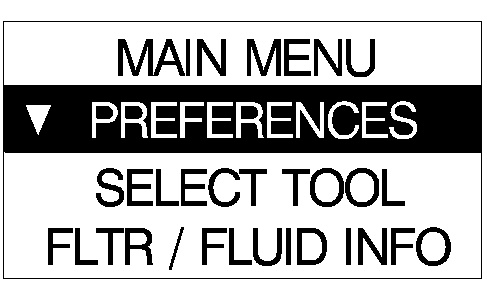
- Press down key (9) in order to highlight the “Select Tool” option. When the “Select Tool” option is highlighted, press the OK key (13) .
|
|
|
|
|
|
| Illustration 8 | g00786650 |
- The current tool is shown. After a few seconds, you will be prompted to enter a password.
- Press “OK” key (13) .
- The current tool is shown after entering the “Select Tool” menu.
|
|
|
|
|
|
| Illustration 9 | g00786666 |
|
This is a typical example. |
|
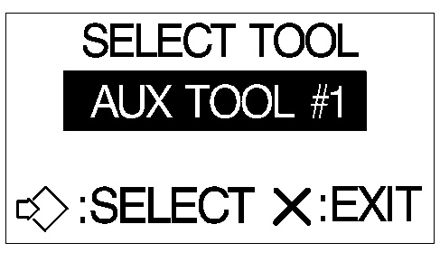
- Press right key (10) or left key (8) in order to scroll through the different tools. Highlight the correct auxiliary tool and press set key (12) .
- Start the engine.
- Place the machine controls at the following settings: engine speed dial at 10, AEC switch OFF. Refer to Testing and Adjusting, “Engine Performance – Test – Engine Speed” for the machine for engine rpm settings.
- Increase the hydraulic oil temperature to 55° ± 5°C (131° ± 9°F).
- Start Service Mode and input a fixed power shift pressure of 2900 kPa (420 psi).
- Press menu key (14) .
Note: The option on the main menu display will be cancelled if thirty seconds or more elapse between keystrokes . The screen is restored to the message display.
- Press down key (9) in order to highlight the menu item “SERVICE OPTIONS” on the message display. Press OK key (13) .
- Input the password “0001”. Press left key (8) or right key (10) in order to change the position of the flashing character. Press up key (7) or press down key (9) in order to change the value of the flashing character. Press OK key (13) after the correct password is displayed.
- Press down key (9) in order to highlight the menu item “ECM SUMMARY” on the message display.
- Press right key (10) repeatedly until “DEVICE TEST” appears on the message display.
- Press down key (9) in order to move down one line on the message display.
- Press right key (10) until the “PS PRV – FIXED” appears on the message display.
- Press down key (9) .
- Press OK key (13) . The display on line 4 of the message display will now change to a numeric value. These characters represent the power shift pressure (kPa).
- Press left key (8) or right key (10) in order to increase or decrease the desired numeric value that is displayed on line 4 of the message display to “2900”. Pressing the left key (8) one time decreases the power shift pressure 10 kPa (1.5 psi). Pressing the right key (10) one time increases the power shift pressure 10 kPa (1.5 psi).
Note: The value for power shift pressure on the monitor may not always match the pressure reading on the pressure gauge. Adjust the value on the monitor until the desired power shift pressure is attained on the pressure gauge that is connected to pressure tap (4) for power shift pressure. The actual power shift pressure must be 2900 kPa (420 psi) on the pressure gauge.
Note: To prevent a change in power shift pressure during the relief valve adjustment, do not turn the engine start switch to the OFF position.
Note: Refer to Service Manual, RENR3814, “Engine and Pump Control System” for additional information on Service Mode.
- Press menu key (14) .
Relief Valve Adjustment for Auxiliary Control Valve (Medium Pressure)
In order to adjust the relief valve pressure, perform the following steps:
|
|
|
|
|
|
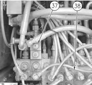
| Illustration 10 | g00993659 |
|
(37) Upper relief valve (38) Main control valve |
|