|
|
|
|
|
|
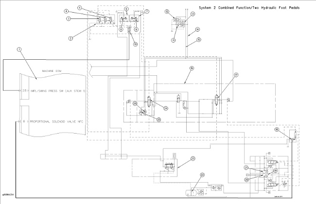
| Illustration 1 | g00864254 |
|
(1) ECM (2) Solenoid valve group (3) Solenoid for one pump/two pump flow (4) Solenoid for one pump/two pump flow (5) Solenoid for one-way/two-way flow (6) Right foot pedal (7) Left foot pedal (8) Right pilot valve (9) Left pilot valve (10) Work tool pressure switch (11) Relief valve (12) Solenoid valve for one-way flow (13) Solenoid valve for one-way flow (14) Line for the work tool (15) Line for the work tool (16) Main control valve (17) Attachment control valve (18) Proportional reducing solenoid valve (19) Pilot pump (20) Drive pump (21) Idler pump (22) Hydraulic tank (23) Pilot manifold (24) Auxiliary control valve (25) Line relief valve (26) Line relief valve |
|
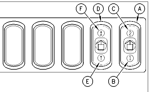
| Switch position “A” for one pump/two pump flow | Switch position “B” for one-way/two-way flow | |
| One pump One-way flow |
B | E |
| One pump Two-way flow |
B | F |
| Two pump One-way flow |
C | E |
| Two pump Two-way flow |
C | F |
The combined function hydraulic system that is present on the excavators that are equipped with a System 2 combines the features of the one-way/two-way flow system with the features of the one pump/two pump flow system.
The one pump flow system allows flow from one pump to power a work tool. All of the load is placed on a single pump. One pump flow is used for work tools that require low flow rates for actuation.
The two pump flow system allows the combined flow from both pumps to power a work tool. Rather than placing all of the load on a single pump, the two pump flow system allows the two pumps to provide flow equally. Two pump flow is used for work tools that require high flow rates for actuation. Two pump flow distributes the load equally for work tools that are used extensively.
A rocker switch is used in order to change between one-way/two-way flow and one pump/two pump flow. The rocker switch assembly is located in the cab of the machines that are equipped with a System 2.
|
|
|
|
|
|
| Illustration 2 | g00994458 |
|
(A) Rocker switch for one pump flow and two pump flow (B) Switch position for one pump flow (C) Switch position for two pump flow (D) Rocker switch for one-way flow and two-way flow (E) Switch position for one-way flow (F) Switch position for two-way flow |
|
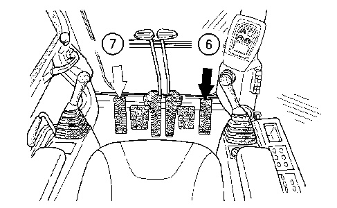
The work tool is operated by two hydraulic foot pedals that are located in the cab.
|
|
|
|
|
|
| Illustration 3 | g00847513 |
|
(6) Right foot pedal for the work tool (7) Left foot pedal for the work tool |
|
One-Way Flow from One Pump “Tool #1”
The default parameter values for “TOOL#1” are for one-way hydraulic oil flow from one main pump. Refer to Testing and Adjusting, “System 2: Default Value of Work Tool Parameters” for the Tool Control System.
The flow to the work tool can be set by using the monitor or ET.
Operation
| Work Tool Circuits and Positions for the Rocker Switches One Pump Flow One-Way Flow |
|
| Rocker Switch (A) | B |
| Rocker Switch (D) | E |
Move rocker switch (A) to position (B) . This de-energizes the solenoid for one pump/two pump flow (3) and the solenoid for one pump/two pump flow (4) . Move rocker switch (D) to position (E) . This energizes the solenoid for one-way flow (12) and the solenoid for one-way flow (13) . This will also de-energize the solenoid for two-way flow (5) .
Pilot pump (19) supplies oil to pilot manifold (23) . When the hydraulic activation lever is moved to the UNLOCK position, pilot oil flows from pilot manifold (23) to right foot pedal (6) . When right foot pedal (6) is depressed FORWARD, pilot oil flows to auxiliary control valve (24) . The pilot oil will shift the spool in auxiliary control valve (24) to the DOWNWARD position. This allows oil from drive pump (20) to flow through the valve. The pump oil flows through the line for the work tool (14) to the work tool. The pump oil flows through the solenoid valve for one-way flow (13) to relief valve (11) . The working pressure for the work tool is limited by relief valve (11) . Return oil flows through the line for the work tool (15) or through the solenoid valve for one-way flow (12) and back to hydraulic tank (22) .
During the operation of the work tool, work tool pressure switch (10) senses pilot pressure.
Pressure switch (10) signals the machine electronic control module . The machine ECM sends a signal to the proportional solenoid valve for negative flow control (18) . Negative flow control pressure in the center bypass passage is blocked when the valve spools shift DOWNWARD. The machine ECM has programmed parameter values “101”, “102”, and “103” for flow and pressure for the work tool. The machine ECM calculates the minimum negative flow control pressure that will be supplied to the pump regulator. When the work tool is activated, proportional solenoid valve (18) receives a signal from the machine ECM. The signal is a result of the calculation. The negative flow control pressure forces the swashplate in the pump to the correct angle to limit the flow and pressure to the work tool.
Note: The pressure setting for the relief valve must be reset to the specification of the supplier for the work tool that is being used.
One-Way Flow From Two Pumps “Tool #3”
Description
The default parameter values for “TOOL#3” are for one-way hydraulic oil flow from two main pumps. Refer to Testing and Adjusting, “System 2: Default Value of Work Tool Parameters” for the Tool Control System.
The flow to the work tool can be set by using the monitor or ET.
Operation
| Work Tool Circuits and Positions for the Rocker Switches Two Pump Flow One-Way Flow |
|
| Rocker Switch (A) | C |
| Rocker Switch (D) | E |
Move rocker switch (A) to position (C) . This energizes the solenoid for one pump/two pump flow (3) and the solenoid for one pump/two pump flow (4) . Move rocker switch (D) to position (E) . This energizes the solenoid for one-way flow (12) and the solenoid for one-way flow (13) . This will also de-energize the solenoid for two-way flow (5) .
Pilot pump (19) supplies oil to pilot manifold (23) . When the hydraulic activation lever is moved to the UNLOCK position, pilot oil flows from pilot manifold (23) to right foot pedal (6) . When right foot pedal (6) is depressed FORWARD, pilot oil flows to auxiliary control valve (24) and to attachment control valve (17) . The pilot oil will shift the spool in auxiliary control valve (24) and attachment control valve (17) to the DOWNWARD position. This allows oil from idler pump (21) to flow through attachment control valve (17) . This also allows oil from drive pump (20) to flow through auxiliary control valve (24) . The hydraulic oil from the two pumps combines after the oil passes through both valves. The pump oil flows through the line for the work tool (14) to the work tool. The pump oil flows through the solenoid valve for one-way flow (13) to relief valve (11) . The working pressure for the work tool is limited by relief valve (11) . Return oil flows through the line for the work tool (15) or through the solenoid valve for one-way flow (12) and back to hydraulic tank (22) .
During the operation of the work tool, work tool pressure switch (10) senses pilot pressure.
Pressure switch (10) signals the machine electronic control module. The machine ECM sends a signal to the proportional solenoid valve for negative flow control (18) . Negative flow control pressure in the center bypass passage is blocked when the auxiliary stems shift DOWNWARD. The machine ECM has programmed parameter values “101”, “102”, and “103” for flow and pressure for the work tool. The machine ECM calculates the minimum negative flow control pressure that will be supplied to the pump regulator. When the work tool is activated, proportional solenoid valve (18) receives a signal from the machine ECM. The signal is a result of the calculation. The negative flow control pressure forces the swashplate in drive pump (20) and idler pump (21) to the correct angle to limit the flow and pressure to the work tool.
Note: The pressure setting for the relief valve must be reset to the specification of the supplier for the work tool that is being used.
Two-Way Flow From One Pump “TOOL#2”
Description
The default parameter values for “TOOL#2” are for two-way hydraulic oil flow from one main pump. Refer to Testing and Adjusting, “System 2: Default Value of Work Tool Parameters” for the Tool Control System.
Operation
| Work Tool Circuits and Positions for the Rocker Switches One Pump Flow Two-Way Flow |
|
| Rocker Switch (A) | B |
| Rocker Switch (D) | F |
Move rocker switch (A) to position (B) . This de-energizes the solenoid for one pump/two pump flow (3) and the solenoid for one pump/two pump flow (4) . Move rocker switch (D) to position (F) . This energizes the solenoid for two-way flow (5) . This will also de-energize the solenoid for one-way flow (12) and the solenoid for one-way flow (13) .
Pilot pump (19) supplies oil to pilot manifold (23) . When the hydraulic activation lever is moved to the UNLOCK position, pilot oil flows from pilot manifold (23) to right foot pedal (6) and to left foot pedal (7) .
When right foot pedal (6) is depressed FORWARD pilot oil flows to auxiliary control valve (24) . The pilot oil will shift the spool in auxiliary control valve (24) to the DOWNWARD position. This allows oil from drive pump (20) to flow through the valve. The pump oil flows through the line for the work tool (14) to the work tool. The working pressure for the work tool is limited by relief valve (25) . Return oil flows through the line for the work tool (15) and back to hydraulic tank (22) .
When left foot pedal control (7) is depressed FORWARD, pilot oil flows from pilot control valve (23) through the solenoid for two-way flow (5) . The pilot oil then flows to auxiliary control valve (24) . The pilot oil shifts the spool in auxiliary control valve (24) in the UPWARD position . This allows oil from drive pump (20) to flow through the valve. The pump oil flows through the line for the work tool (15) to the work tool. The working pressure for the work tool is limited by relief valve (26) . Return oil flows through the line for the work tool (14) back to hydraulic tank (22) .
Note: The pressure setting for the relief valves must be reset to the specification of the supplier for the work tool that is being used.
Two-Way Flow From Two Pumps “TOOL#4” and “TOOL#5”
Description
The default parameter values for “TOOL#4” and “Tool #5” are for two-way hydraulic oil flow from two main pumps. Refer to Testing and Adjusting, “System 2: Default Value of Work Tool Parameters” for the Tool Control System.
Operation
| Work Tool Circuits and Positions for the Rocker Switches Two Pump Flow Two-Way Flow |
|
| Rocker Switch (A) | C |
| Rocker Switch (D) | F |
Move rocker switch (A) to position (C) . This energizes the solenoid for one pump/two pump flow (3) and the solenoid for one pump/two pump flow (4) . Move rocker switch (D) to position (F) . This energizes the solenoid for two-way flow (5) . This will also de-energize the solenoid for one-way flow (12) and (13) .
Pilot pump (19) supplies oil to pilot manifold (23) . When the hydraulic activation lever is moved to the UNLOCK position, pilot oil flows from pilot manifold (23) to right foot pedal (6) and to left foot pedal (7) .
When right foot pedal (6) is depressed FORWARD, pilot oil flows to auxiliary control valve (24) and to attachment control valve (17) . The pilot oil will shift the spool in the auxiliary control valve (24) and attachment control valve (17) to the DOWNWARD position. This allows oil from idler pump (21) to flow through attachment control valve (17) and this allows oil from drive pump (20) to flow through auxiliary control valve (24) . The hydraulic oil from the two pumps combines after the oil passes through both valves. The pump oil flows through the line for the work tool (14) to the work tool. The working pressure for the work tool is limited by relief valve (25) . Return oil flows through the line for the work tool (15) and back to hydraulic tank (22) .
When left foot pedal (7) is depressed FORWARD, pilot oil flows from pilot control valve (23) through the solenoid for two-way flow (5) . The pilot oil then flows to auxiliary control valve (24) and to attachment control valve (17) . The pilot oil shifts the spool in each of the valves to the UPWARD position. This allows oil from idler pump (21) to flow through attachment control valve (17) and this allows oil from right pump (20) to flow through auxiliary control valve (24) . The hydraulic oil from the two pumps combines after the oil passes through both valves. The pump oil flows through the line for the work tool (15) to the work tool. The working pressure for the work tool is limited by relief valve (26) . Return oil flows through the line for the work tool (14) back to hydraulic tank (22) .
Note: The pressure setting for the relief valves must be reset to the specification of the supplier for the work tool that is being used.