Specification
Note: Certain machines will default to “Economy Mode” at machine startup. Change to “High Hydraulic Power Mode” before performing the test procedure.
| “Travel Motor – Test (Measurement of Case Drain Oil)” | |||
|---|---|---|---|
| Machine Settings | Crossover Relief Pressure | Engine Speed | |
| 36800 ± 1500 kPa (5340 ± 220 psi) | Engine speed dial “10” AEC switch OFF |
||
| Item | Specification (1) | Left Travel | Right Travel |
| New Travel Motor | 38 L/min (10.1 US gpm) | 1. | 1. |
| 2. | 2. | ||
| 3. | 3. | ||
| Rebuilt Travel Motor | 38 L/min (10.1 US gpm) | 1. | 1. |
| 2. | 2. | ||
| 3. | 3. | ||
| ( 1 ) | Maximum acceptable flow |
Introduction
Use the following procedure in order to measure the case drain of the travel motors.
|
|
| NOTICE |
|---|
|
Care must be taken to ensure that fluids are contained during performance of inspection, maintenance, testing, adjusting, and repair of the product. Be prepared to collect the fluid with suitable containers before opening any compartment or disassembling any component containing fluids. Refer to Special Publication, NENG2500, “Dealer Service Tool Catalog” for tools and supplies suitable to collect and contain fluids on Cat products. Dispose of all fluids according to local regulations and mandates. |
|
|
Required Tools
|
|
|
|
|
|
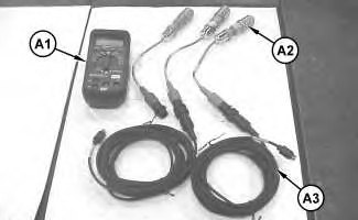
| Illustration 1 | g02571852 |
|
Tooling (A) 198-4240 Digital Pressure Indicator Gp |
|
|
|
|
|
|
|
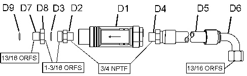
| Illustration 2 | g02709177 |
|
Tooling group (D) |
|
| Required Tools | ||||
|---|---|---|---|---|
| Tool | Item | Qty | Part Number |
Description |
| A | 198-4240 | Digital Pressure Indicator Gp | ||
| A1 | 1 | 198-4234 | Indicator | |
| A2 | 1 | 198-4237 | Pressure Sensor
3447 kPa (500 psi) |
|
| A2 | 1 | 198-4239 | Pressure Sensor
41,368 kPa (6,000 psi) |
|
| A3 | 2 | 198-4236 | Extension Cable | |
| D | D1 | 1 | 6V-7788 | Flow Meter
5 to 60 L/min (2 to 15 US gpm) |
| D2 | 1 | 8C-6874 | Reducer | |
| D3 | 1 | 6V-9746 | O-Ring Seal | |
| D4 | 1 | 124-1901 | Permanent Coupling | |
| D5 | 3 ft | 122-6870 | Bulk Hydraulic Hose | |
| D6 | 1 | 124-2147 | Permanent Coupling | |
| D7 | 1 | 6V-8942 | O-Ring Reducer | |
| D8 | 1 | 6V-8556 | Nut | |
| D9 | 1 | 6V-8398 | O-Ring Seal | |
| F | 1 | 311-1362 | Vacuum Cap | |
| G | 1 | 418-3612 | Track Block | |
Machine Preparation
- Position the machine on level ground.
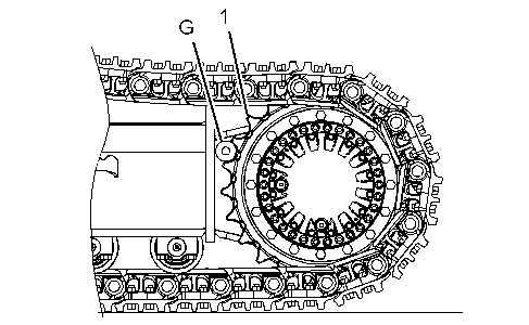
- Place track block (G) in sprocket (1) in order to block forward left travel. Refer to Illustration 3.
|
|
|
|
|
|
| Illustration 3 | g03267696 |
|
Sprocket (left travel) (G) Track block (1) Sprocket |
|
- Stop the engine.
- Release the pressure in the hydraulic system. Refer to Testing and Adjusting, “Hydraulic System Pressure – Release”.
- Attach 311-1362 Vacuum Cap onto the hydraulic tank. Attach an air supply hose onto the assembly. Apply 276 to 414 kPa (40 to 60 psi). This procedure will pull a vacuum on the hydraulic system.
- Install the following tools in accordance with the flow meter tool layout. Refer to Illustration 4.
|
|
|
|
|
|
| Illustration 4 | g02240294 |
|
Flow Meter Tool Layout Tooling (D) (2) Case drain hose (3) Connector (4) Travel motor |
|
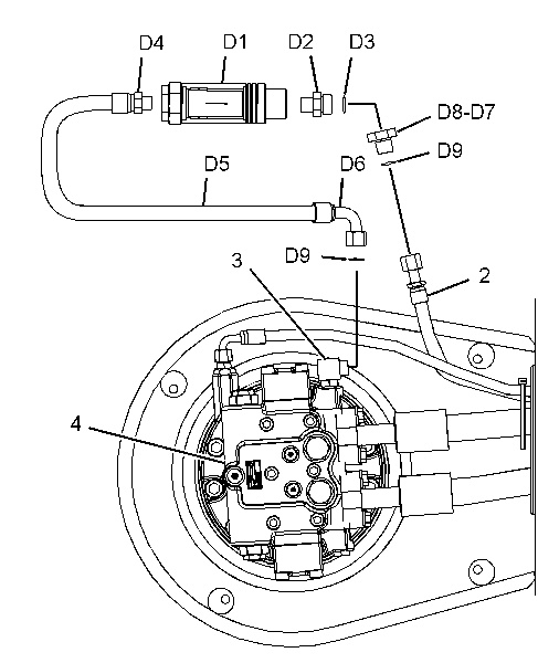
- Disconnect case drain hose (2) from connector (3) .
- Connect the flow meter assembly (D) between connector (3) and case drain hose (2) .
Note: Correct orientation of the flow meter is necessary. The oil flows from travel motor (4) to case drain hose (2) .
- Remove 311-1362 Vacuum Cap and install the filler plug for the hydraulic tank.
Test Procedure
- Start the engine.
- Place the machine controls at the following settings: engine speed dial “10” and AEC switch OFF. Refer to Testing and Adjusting, “Engine Performance – Test (Engine Speed)” for engine rpm settings.
- Increase the hydraulic oil temperature to 55° ± 5°C (131° ± 9°F).
- Move the left travel lever to full FORWARD position and check the flow of oil through the flow meter.
- Remove track block (G) from sprocket (1) .
- Move the left travel lever in order to reposition the travel motor.
- Place track block (G) in sprocket (1) in order to block forward left travel.
- Repeat Steps 4 through 7 in order to obtain three measurements of case drain oil.
The maximum acceptable flow of case drain oil when the travel crossover relief valves are set at 36800 ± 1500 kPa (5340 ± 220 psi). … 38 L/min (10.1 US gpm)