Electronic Control Module (ECM)
|
|
|
|
|
|
| Illustration 1 | g01458173 |
|
PL300 ECM with 70 pin Wiring Harness Connector Installed |
|
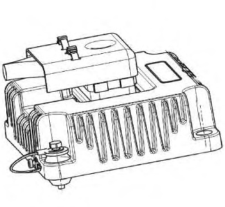
The Product Link PL300 is an electronic control module (ECM). The ECM is initially setup by using a laptop computer with the Caterpillar Electronic Technician (Cat ET) software. The PL300 is designed for use with the PL121SR radio. PL321SR is the designation for the system that uses both the PL121SR radio and the PL300 ECM. In order to use the new Product Link features, update to the latest version of Cat ET. Refer to Special Instruction, REHS2365 for more information on installing the PL121SR and the PL300.
The Product Link PL121SR provides the customer with location, SMH (Service Meter Hour), and Geo-Fencing communication and configuration capabilities.
The Product Link PL321SR provides the customer with the capabilities of the PL121SR system and with the capability of the PL300 ECM to communicate and configure the diagnostic codes, events, and other Cat Datalink® information.
A Product Link PL121SR system can be converted to a Product Link PL321SR system by adding the PL300 ECM to the PL121SR radio.
Ensure that the Product Link PL300 module is installed with the available shock mount kit.
Inputs
The Product Link PL300 can be set up to receive information from components about machine operations by using switch to ground type inputs. Switches provide ON or OFF (closed or open) signals to the switch inputs of the Product Link. The inputs to the Product Link are listed in the table for the 70 pin connector. Refer to Systems Operation, Troubleshooting, Testing and Adjusting, “Spare Inputs” for more information.
Input/Output
The Product Link PL300 uses the Cat Datalink® in order to communicate with other electronic control modules. The data link is bidirectional. The data link allows the PL300 to receive information. The data link also allows the PL300 to send information.
A module identifier (MID) is assigned to each ECM. The MID for the PL300 is the number 122.
| Product Link Contact Description | ||
|---|---|---|
| Contact Number | Function | Type |
| 34 | CAN Low | Input |
| 50 | CAN High | Input |
| 42 | CAN Shield | Input |
| 52 | + Battery | Power |
| 65 | Ground | Ground |
| 54 | Alternator R -Terminal | Input |
| 70 | Key switch | Input |
| 8 | Cat Datalink + | Input/Output |
| 9 | Cat Datalink – | Input/Output |
| 45 | Spare Digital Input 1 | Switch Input (Open/Ground) |
| 46 | Spare Digital Input 2 | Switch Input (Open/Ground) |
| 47 | Spare Digital Input 3 | Switch Input (Open/Ground) |
| 55 | Spare Digital Input 4 | Switch Input (Open/Ground) |
PL121SR Radio
|
|
|
|
|
|
| Illustration 2 | g01121196 |
|
Mounting method for the PL121SR Radio |
|
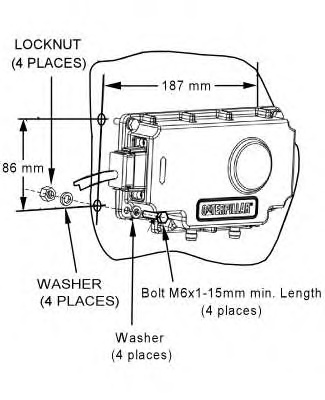
The antennas that can be used on the PL121SR are for satellite communication system and for the GPS system.
Shock mounting is not required or available for the PL121SR radio.
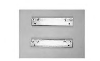
Adapter Plates
The adapter plates allow a dealer to mount a PL300 in a place originally planned for a PL151/PL201.
|
|
|
|
|
|
| Illustration 3 | g01104288 |
|
PL300 ECM Adapter Plates |
|
Wiring Harnesses
The installation kit includes the control harness assembly. The wiring harness is enclosed in a protective braided cover.
Radio Harness
|
|
|
|
|
|
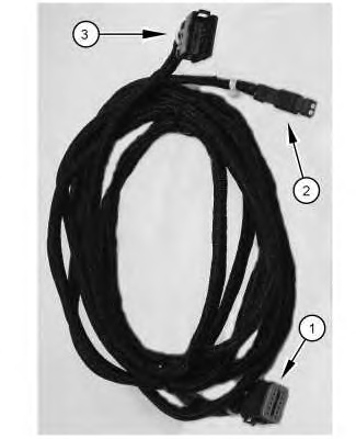
| Illustration 4 | g01103872 |
|
2 m (6.6 ft) PL121SR Radio Harness (1) 12-pin plug connector (P1) (2) 2-pin receptacle connector (J2) (3) 12-pin receptacle connector (J1) |
|
ECM Harness
|
|
|
|
|
|
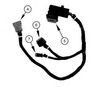
| Illustration 5 | g01336465 |
|
(4) 12-pin receptacle connector (J1) (5) 70-socket plug connector (P1) (6) 12-socket plug connector (P2) (7) 2-socket plug connector (P3) |
|
Conversion Harness
|
|
|
|
|
|
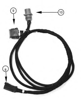
| Illustration 6 | g01336474 |
|
(8) 6-pin receptacle connector (J1) (9) 12-pin plug connector (P1) (10) 3-pin round receptacle connector (J2) |
|
Legacy Harness
|
|
|
|
|
|
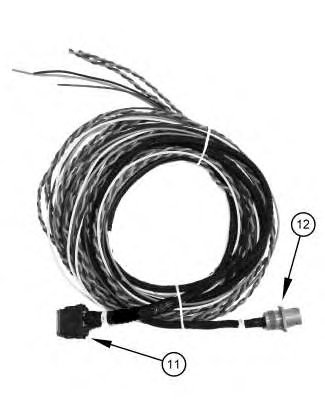
| Illustration 7 | g01336488 |
|
(11) 12-pin plug connector (P1) (12) 3-pin receptacle connector (J1) |
|