Cat Undercarriage Management Guide Page 12
Management Guide
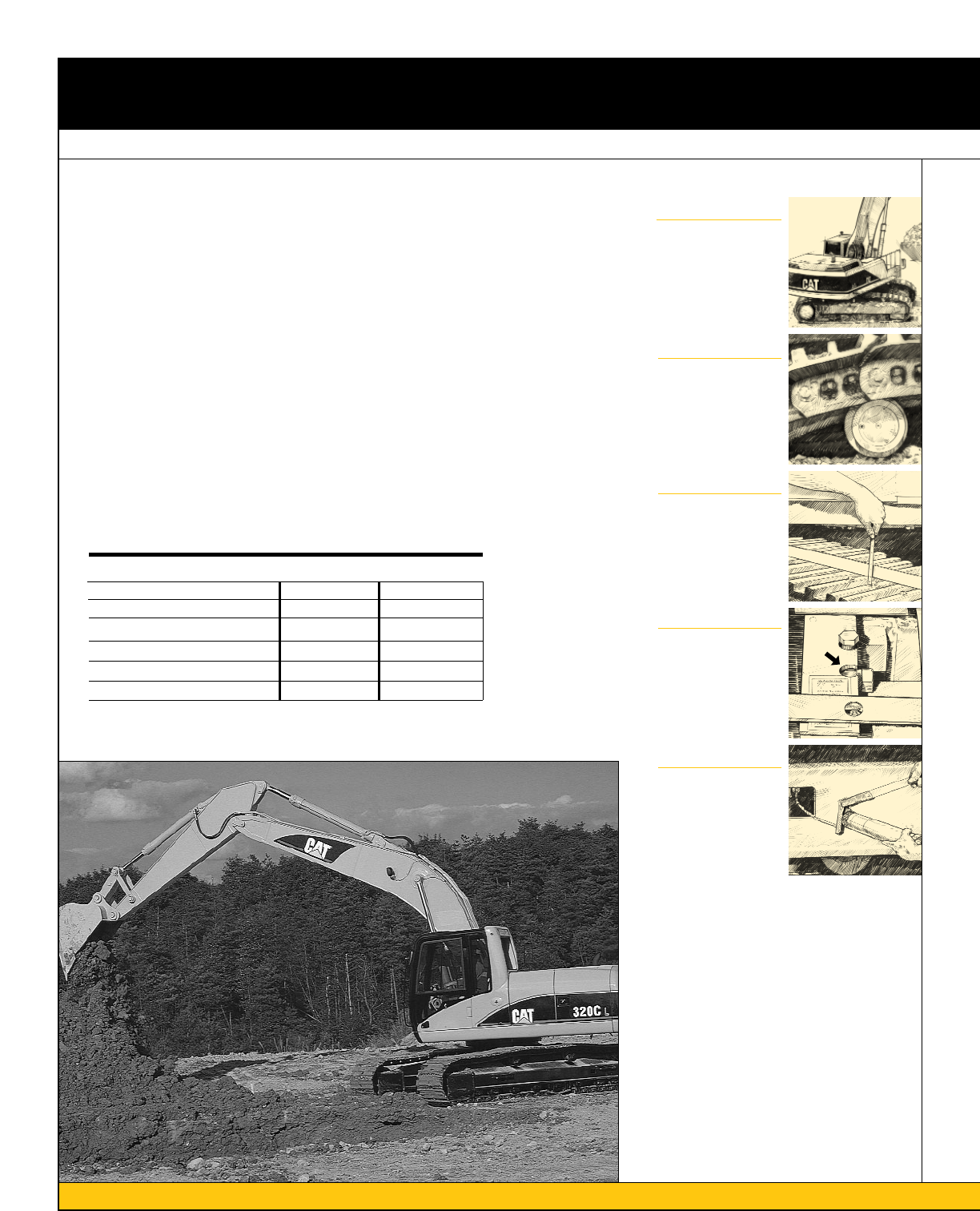
Track Adjustment Procedures
12
Hydraulic Excavators
1.
Operate the machine in the direction
of the idlers.
2.
Stop with one track pin directly over
the front carrier roller. Park the
machine and turn off the engine.
3.
Place a tight line or straight edge on
top of the grousers between the front
carrier roller and idler.
Measure the distance from the straight
edge to the grouser tip at the lowest
point of sag, midway between the front
carrier roller and idler.
Refer to Chart 4 to determine the
correct sag for each model.
4.
If the track is too tight, loosen it by
opening the relief valve and allowing
grease to escape.
5.
Tighten track by adding grease at the
hydraulic fill and relief valve. Travel in
forward and reverse to equalize tension
throughout the track. Then reinspect
adjustment.
1
2
3
4
5
Chart 4
Proper Track Sag
Inches Millimeters
Model Min Target Max Min Target Max
All 200-Family series excavators 1.0 1.3 1.5 25.0 32.5 40.0
All E-Family series excavators 1.6 1.85 2.1 40.0 47.5 55.0
All 300-Family series excavators 1.6 1.85 2.1 40.0 47.5 55.0
5080, 5090B, 5130, 5130B, 5110B 1.6 1.85 2.1 40.0 47.5 55.0
Contents Summary of Cat Undercarriage Management Guide
- Page 1Cat Undercarriage ® Management Guide Caterpillar. The difference counts.™ Undercarriage System Management • Operating and Maintenance Tips • Track Adjustment Procedures • Hardware Requirements
- Page 2Contents Introduction.............................................................................................................................3 Operating and Maintenance Tips ........................................................................................4-7 Custom Track Service Factors
- Page 3Introduction Work it hard. Make it last. Fix it right. Caterpillar® Undercarriage is designed to work and wear as a system to reduce your operating costs. You make daily decisions that impact undercarriage wear and costs. This guide can help you and your operators understand how undercarriage works
- Page 4Operating and Maintenance Tips Custom Track Service Factors Affecting Wear Your undercarriage is an expensive While there is no substitute for Application investment. It accounts for as much Custom Track Service, you also play Application describes what your as 20 percent of the price of a new an im
- Page 5Packing Terrain During operation, materials can Most of the time you can’t control the Working on a side hill shifts the stick to and pack between mating terrain you are working in. However, weight and load balance to the components such as rollers, links, it is important to understand how downhill
- Page 6Operating and Maintenance Tips Factors Affecting Wear Control the operation of your machine One of the best ways to protect your machine against unnecessary wear is to make sure it is used properly. All of the following cause additional wear on the components of your Always use the narrowest shoe po
- Page 7Be sure your track is always properly adjusted Operating Checklist Every application affects Improperly adjusted track can result undercarriage wear differently and in problems and wear on other requires proper track adjustment. components such as: Adjust your track in the underfoot ❏ 1. Always use
- Page 8Track Adjustment Procedures Elevated Sprocket Tractors Incorrectly adjusted track can cost 1. Move the tractor forward and let it 1 you money both in accelerated coast to a stop without applying the undercarriage wear and downtime. brakes. Make sure slack is between If the track is too tight, damagi
- Page 9Chart 1 Chart 3 Proper Track Sag Track Roller Frame Extension Specifications Machines without carrier rollers Machines with and without carrier rollers Max. Length of Inches Millimeters Exposed Tube Model Min Target Max Min Target Max Model (Serial Number Range) Inches Millimeters D11R, D11N, D10 6.
- Page 10Track Adjustment Procedures Low Sprocket Tractors and Loaders 1. Move the machine forward and let On machines with more than one 1 it coast to a stop without applying the carrier roller per side, mark the track brakes. Then park the machine and roller frame .5 inch or 13 millimeters turn off the eng
- Page 11Hydrostatic Loaders 1. Move the machine forward and let 5. Open the relief valve and let the 1 it slowly come to a stop. Then park idler drift back until the second mark the machine and turn off the engine. is behind the recoil housing. Then Place a tight line over the grouser close the relief valve
- Page 12Track Adjustment Procedures Hydraulic Excavators 1. Operate the machine in the direction 4. If the track is too tight, loosen it by 1 of the idlers. opening the relief valve and allowing 2. Stop with one track pin directly over grease to escape. the front carrier roller. Park the 5. Tighten track by
- Page 13Hardware Requirements Track Roller and Idler Caps Inadequate clamping of the track roller 3. Snug both bolts evenly prior to and idler caps can result in broken torquing. retaining bolts and damage to the 4. Tighten the bolts to the specified frame or bogie bore. torque shown in the charts below. To
- Page 14Hardware Requirements Shoe and Link Split Master Link The number one cause of shoe 3. Tighten the bolts to the specified The importance of correctly loosening is improperly tightened shoe initial torque shown in the chart below. assembling and torquing cannot hardware. In general, track hardware 4.
- Page 15Notes 15�
- Page 16Expect More from the Experts When you buy a Cat undercarriage system, you get the support of our parts and service representatives who have tools to help you manage your undercarriage system. Custom Track Service (CTS) is the best way to control costs and downtime. While there is no substitute for C