C32 Power Module Operation and Maintenance Manual Page 51
Operation and
Maintenance
Manual
SEBU8219-01 51
Operation Section
Features and Controls
Digital Input 2
– Digital Input 2 is used for remotely
starting and stopping the generator set. This input
should be wired to GROUND through a switch that
canbeinitiat
ed remotely. The input can be set to
activate on an active high (normally closed contact)
or an active low (normally open contact). If the input
is active and
theengineisinAUTO,theenginewill
attempt to start. Once the input becomes inactive the
engine will enter into cooldown mode (if programmed)
and then the
engine will stop.
The remainder of the inputs can be configured. The
main purpos
e for the other “DIGITAL” inputs is to add
additional monitoring capabilities of the parameters
for the engine or generator. The inputs can be
configured b
y going to the “EVENT I/P FUNCTIONS”
parameter under the “SETPOINTS” menu. The
“DIGITAL INPUTS” parameter can only be set to
“ACTIVE HI
GH” or “ACTIVE LOW” in order to initiate
a High Warning, Low Warning, High Shutdown, Low
Shutdown, or Status.
The inputs can be programmed to monitor the
following parameters or components. Refer to
System Op
eration, Troubleshooting, Testing and
Adjusting, RENR7902, “Digital Input Programming”.
Pressure
s
•
Air filter differential pressure
•
Engine oil pressure
•
Fire exti
nguisher pressure
•
Fuel filter differential pressure
•
Oil filter differential pressure
•
Starting
air pressure
Temperatures
•
Ambient air temperature
•
Engine co
olant temperature
•
Engine oil temperature
•
Exhaust temperature
•
Rear bear
ing temperature (C32 only)
•
Right exhaust temperature
•
Left exhaust temperature
Levels
•
Engine coolant level
•
Engine oil leve
l
•
Fuel level
•
External fuel tank level
Other
•
Air damper closed
•
ATS in normal position
•
ATS in emergen
cy position
•
Battery charger failure
•
Generator breaker closed
•
Utility break
er closed
•
Fuel leak detected
•
Custom event
For detailed i
nformation about the electronic control
module, see Systems Operation, Troubleshooting,
Testing and Adjusting, RENR7902, “EMCP3”.
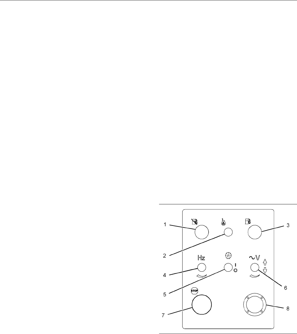
Control Panel
g01220625
Illustration 51
C27
(1) Pump stop switch
(2) Starting aid auto/manual switch (optional)
(3) Pump run switch
(4) Speed potentiometer (optional)
(5) Panel light switch
(6) Voltage adjus t switch
(7) Emergen cy stop push button
(8) Diagnostic connector
Contents Summary of C32 Power Module Operation and Maintenance Manual
- Page 1SEBU8219-01 June 2008 Operation and Maintenance Manual C32 Power Module MED1-Up (Power Module) MEG1-Up (Power Module) SAFETY.CAT.COM
- Page 2i01658146 Important Safety Information Most accidents that involve product operation, maintenance and repair are caused by failure to observe basic safety rules or precautions. An accident can often be avoided by recognizing potentially hazardous situations before an accident occurs. A person must b
- Page 3SEBU8219-01 3 Table of Contents Table of Contents Setup Procedures ................................................. 69 Transportation Information .................................... 71 Foreword ................................................................. 4 Maintenance Section Safety Section R
- Page 44 SEBU8219-01 Foreword Foreword Use fuel consumption or service hours to determine intervals. Calendar intervals shown (daily, annually, etc.) may be used instead of service meter intervals Literature Information if they provide more convenient schedules and approximate the indicated service meter r
- Page 5SEBU8219-01 5 Foreword California Proposition 65 Warning Diesel engine exhaust and some of its constituents are known to the State of California to cause cancer, birth defects, and other reproductive harm. Battery posts, terminals and related accessories contain lead and lead compounds. Wash hands a
- Page 66 SEBU8219-01 Safety Section Safety Messages Safety Section i03085837 Safety Messages SMCS Code: 1000; 7405 g01567702 Illustration 1 C32 Generator Set
- Page 7SEBU8219-01 7 Safety Section Safety Messages g01452725 Illustration 2 PM1000
- Page 88 SEBU8219-01 Safety Section Safety Messages g01452776 Illustration 3 XQ1000 g01398172 Illustration 4 PM1000
- Page 9SEBU8219-01 9 Safety Section Safety Messages g01452731 Illustration 5 XQ1000 Universal Warning (1) Automatic Starting (2) The universal safety message is located on each The safety message for automatic starting is located side of the generator enclosure and on each side of on each side of the enclo
- Page 1010 SEBU8219-01 Safety Section Safety Messages Hot Surface (3) Lifting the Genset (4) The safety message for a hot surface is located on This safety message for lifting the genset is located each side of the radiator and on each side of the on right, left, and rear panels of the generator barrel of t
- Page 11SEBU8219-01 11 Safety Section Safety Messages Hot Fluid Under Pressure (5) Electrocution (6) The safety message for hot fluid under pressure is The safety message for electrocution is located on located on top of the radiator near the radiator cap. the sides of the terminal box, on the doors of the
- Page 1212 SEBU8219-01 Safety Section Additional Messages Access Door (7) i02798447 The safety message for the access door to the Additional Messages camlock panel is located on the access door to the camlock panel. SMCS Code: 1000; 7405 There are several specific messages on this machine. The exact locatio
- Page 13SEBU8219-01 13 Safety Section Additional Messages g01398274 Illustration 6 C32 is shown. g01398277 Illustration 7 C32 is shown. Lifting Point(1)
- Page 1414 SEBU8219-01 Safety Section General Hazard Information This message is located on both sides of the enclosure. g01398331 Illustration 10 g01398322 This is the location of a coolant drain. Illustration 8 This is the location of a lifting point. i02566298 Oil Drain(2) General Hazard Information This
- Page 15SEBU8219-01 15 Safety Section General Hazard Information Engine exhaust contains products of combustion Unless other instructions are provided, perform which may be harmful to your health. Always start the the maintenance under the following conditions: engine and operate the engine in a well ventil
- Page 1616 SEBU8219-01 Safety Section General Hazard Information Containing Fluid Spillage • Avoid brushing materials that contain asbestos. Care must be taken in order to ensure that fluids • Avoid grinding materials that contain asbestos. are contained during performance of inspection, maintenance, testin
- Page 17SEBU8219-01 17 Safety Section Burn Prevention i02088921 i02469590 Burn Prevention Fire Prevention and Explosion SMCS Code: 1000; 4450; 7405 Prevention SMCS Code: 1000; 4450; 7405 Do not touch any part of an operating engine. Allow the engine to cool before any maintenance is performed on the engine.
- Page 1818 SEBU8219-01 Safety Section Fire Prevention and Explosion Prevention Do not weld on lines or tanks that contain flammable fluids. Do not flame cut lines or tanks that contain flammable fluid. Clean any such lines or tanks thoroughly with a nonflammable solvent prior to welding or flame cutting. Wi
- Page 19SEBU8219-01 19 Safety Section Crushing Prevention and Cutting Prevention Do not store ether cylinders in living areas or in the Unless other maintenance instructions are provided, engine compartment. Do not store ether cylinders never attempt adjustments while the engine is in direct sunlight or in
- Page 2020 SEBU8219-01 Safety Section Engine Starting Overspeed shutdown should occur automatically. Always start the engine according to the procedure If automatic shutdown does not occur, press the that is described in the Operation and Maintenance emergency stop button in order to cut the fuel and/or Man
- Page 21SEBU8219-01 21 Safety Section Electrical System i02106213 i01593543 Electrical System Generator Isolating for SMCS Code: 1000; 1400 Maintenance SMCS Code: 4450 Never disconnect any charging unit circuit or battery circuit cable from the battery when the charging unit When you service an electric pow
- Page 2222 SEBU8219-01 Safety Section Generator Isolating for Maintenance 9. Determine that the generator is in a de-energized condition. Add ground straps to the conductors or terminals. During the entire work period, these ground straps must remain connected to the conductors and to the terminals.
- Page 23SEBU8219-01 23 Product Information Section General Information Product Information Section General Information i02640420 Welding on Engines with Electronic Controls SMCS Code: 1000 NOTICE Proper welding procedures are necessary in order to avoid damage to the engine’s ECM, sensors, and associated co
- Page 2424 SEBU8219-01 Product Information Section Model Views and Specifications Model Views and Specifications i02787919 Model View Illustrations SMCS Code: 1000; 4450 The following model views show typical features of the generator set and power module that are supported in this manual. Due to individual
- Page 25SEBU8219-01 25 Product Information Section Model Views and Specifications g01392665 Illustration 22 Typical example of a C32 power module (1) Paralleling panel (6) DC light (11) Spill containment pan (2) Precleaner (7) Coolant filler access panel (12) Fuel transfer pump (3) AC light (8) Service ladd
- Page 2626 SEBU8219-01 Product Information Section Model Views and Specifications g01394417 Illustration 23 Typical example of a C32 power module (1) Paralleling panel access door (5) Spare/blank port (9) Camlock panel access door (2) Air intake louver (6) Fuel onload/offload (10) Breaker panel access door
- Page 27SEBU8219-01 27 Product Information Section Model Views and Specifications g01396505 Illustration 24 Rear view (1) RC panel (3) Battery charger (2) House keeping/fuel control panel (4) Distribution panel
- Page 2828 SEBU8219-01 Product Information Section Model Views and Specifications g01396534 Illustration 25 Typical example of a C32 Power Module (1) Radiator (5) AC lighting (9) 4732 L (1250 US gal)Fuel tank (2) Muffler (6) DC lighting (10) Fuel transfer pump (3) Battery charger (7) Control panel (11) Main
- Page 29SEBU8219-01 29 Product Information Section Model Views and Specifications g01395244 Illustration 26 Typical example of a C32 power module (1) Access door (3) External fuel connection (5) Oil drain (2) Louver (4) Radiator drain
- Page 3030 SEBU8219-01 Product Information Section Model Views and Specifications g01394563 Illustration 27 Typical example of a C32 power module (1) Louver (2) Access door (3) Load cable access i02792970 Electronic Engine Features Product Description Caterpillar C32 engines are designed with electronic con
- Page 31SEBU8219-01 31 Product Information Section Model Views and Specifications • System diagnostics For more information on electronic engine features, refer to the Operation and Maintenance Manual, “Features and Controls” topic (Operation Section). Engine Cooling and Lubrication The cooling system consi
- Page 3232 SEBU8219-01 Product Information Section Model Views and Specifications SR4B generators are utilized in three-phase full-wave Louvers excitation and regulation. The generators are four-pole generators with four, six, ten, or twelve lead Louvers are installed in the power module in order configurat
- Page 33SEBU8219-01 33 Product Information Section Model Views and Specifications The fuel transfer pump requires a specific minimum Net Positive Suction Head Available (NPSHA) to properly operate. The NPSHA can be estimated by adding the static suction head and the dynamic restrictions that are in the syst
- Page 3434 SEBU8219-01 Product Information Section Product Identification Information Product Identification Engine Identification Plate (2) Information The engine identification plate is located on the right side of the engine on the oil cooler. i02793310 Setpoint of the engine altitude derate ____________
- Page 35SEBU8219-01 35 Product Information Section Product Identification Information g00776690 Illustration 31 i02331504 The top level part numbers in the Parts Manual for the engine are listed with the engine arrangement Reference Information number. Occasionally, an arrangement may be slightly modified b
- Page 3636 SEBU8219-01 Product Information Section Product Identification Information The performance specification can be used by Wye Configuration Diagram your Caterpillar dealer with the Technical Marketing Information system. Before the engine leaves the 6 Lead factory, the engine performance is tested.
- Page 37SEBU8219-01 37 Product Information Section Product Identification Information Grounding the Frame In applications where definite measures are taken in order to prevent grounds to the load leads, an In any generator set installation, the frame of the ungrounded neutral can be used. Be sure to check g
- Page 3838 SEBU8219-01 Product Information Section Product Identification Information Wye Configuration Diagrams 6 Lead g00611608 Illustration 36 12 Lead Wye Configuration - Low Voltage g00611486 Terminals T10, T11 and T12 become neutral connection when Illustration 34 the terminals are tied together. 6 Lea
- Page 39SEBU8219-01 39 Product Information Section Product Identification Information 12 Lead If the neutral wire is grounded and one of the phase leads becomes grounded, the excessive current will open a load circuit breaker. The excessive current will also collapse the generator voltage. The result depend
- Page 4040 SEBU8219-01 Product Information Section Product Identification Information Parallel to Utility Wye Configuration Diagrams When a Wye connected generator is going to operate 6 Lead Generators in parallel with a utility system (infinite bus) and when the secondary of the step-down transformer in th
- Page 41SEBU8219-01 41 Product Information Section Product Identification Information 12 Lead Generators g00637320 Illustration 41 g00626130 Typical Parallel Wye Configuration (60 Hz, 12 Lead) Illustration 43 This is a typical high voltage connection. Typical Delta Configuration (60 Hz, 12 Lead) Delta Confi
- Page 4242 SEBU8219-01 Product Information Section Product Identification Information Do not exceed the nameplate current rating for any Delta Configuration Diagrams one phase. 6 Lead Generators Wye Configuration Diagrams 6 Lead Generators g00626135 Illustration 46 Single-Phase Voltage Diagram with 6 Lead D
- Page 43SEBU8219-01 43 Operation Section Lifting and Storage Operation Section Lifting the Entire Package Do NOT use the engine lifting eyes or the generator lifting eyes to lift the entire package. Lifting and Storage Lifting points (3) have been provided on the base rails of the generator set for lifting
- Page 4444 SEBU8219-01 Operation Section Lifting and Storage i02147124 For more detailed information on engine storage, see Special Instruction, SEHS9031, “Storage Procedure Product Storage for Caterpillar Products”. SMCS Code: 7002 Generator Storage Short Time Storage A storage period in excess of six mont
- Page 45SEBU8219-01 45 Operation Section Lifting and Storage For additional information on generator storage, consult your Caterpillar dealer for assistance.
- Page 4646 SEBU8219-01 Operation Section Installation Installation Storage Short Time Storage i01856938 Generator Set Installation If the generator is not installed immediately, store the generator in a clean area. This area should also SMCS Code: 7002 have the following conditions: low humidity, stable hum
- Page 47SEBU8219-01 47 Operation Section Installation • Well ventilated Protective Devices • Easily accessible for inspection and maintenance The output to the load of the generator should always be protected with an overload protection device such Do not obstruct air inlet openings. Do not obstruct as a ci
- Page 4848 SEBU8219-01 Operation Section Features and Controls Features and Controls i02553580 Programmable System Parameters SMCS Code: 1900 Record your customer programmed parameters for reference. Table 3 Parameters that may be Programmed by the Customer Customer Programmed Parameters Equipment ID Engine
- Page 49SEBU8219-01 49 Operation Section Features and Controls i02443021 Electronic Modular Control Panel 3 (EMCP 3) SMCS Code: 4490 Electronic Control Module (Generator Set) g01045431 Illustration 50 (1) Display screen (7) Lamp test key (13) Right key (2) AC overview key (8) Run key (14) Enter key (3) Engi
- Page 5050 SEBU8219-01 Operation Section Features and Controls RUN Key (8) – Pressing the “RUN” key will start Left Key (16) – The “LEFT” key is used during the engine. setpoint adjustment. The “LEFT” key is used to select the digit that is edited during the entry of numeric AUTO Key (9) – Pressing the “AUT
- Page 51SEBU8219-01 51 Operation Section Features and Controls Digital Input 2 – Digital Input 2 is used for remotely • Engine oil level starting and stopping the generator set. This input should be wired to GROUND through a switch that • Fuel level can be initiated remotely. The input can be set to activat
- Page 5252 SEBU8219-01 Operation Section Features and Controls Note: Your application may not have all of these features. Pump Stop Switch (1) – The pump stop switch is optional. The pump stop switch is used to manually stop the fuel transfer pump. Fully depress the switch in order to latch the switch. The
- Page 53SEBU8219-01 53 Operation Section Features and Controls Annunciator Module To acknowledge the shutdown and alarm conditions or to silence the horn, press the “Alarm Acknowledge” button that is located near the middle of the annunciator. To test the LED indicators or to test the horn when the data lin
- Page 5454 SEBU8219-01 Operation Section Engine Starting Engine Starting • Do not start the engine or move any of the controls if there is a “DO NOT OPERATE” warning tag or similar warning tag attached to the start switch or i02048636 to the controls. Before Starting Engine • Ensure that the areas around th
- Page 55SEBU8219-01 55 Operation Section Engine Starting Startability will be improved at temperatures below 10°C (50°F) from the use of a cylinder block coolant NOTICE heater or from other means that are used to heat Oil pressure should rise within 15 seconds after the the crankcase oil. Some engine applic
- Page 5656 SEBU8219-01 Operation Section Engine Starting i01934760 5. Immediately after the stalled engine is started, disconnect the jump start cables in reverse order. Starting with Jump Start Cables Note: If there is a problem with the alternator or the battery charger, the engine will not continue to ru
- Page 57SEBU8219-01 57 Operation Section Engine Operation Engine Operation i01136207 Fuel Conservation Practices i01646252 SMCS Code: 1000; 1250 Engine Operation The efficiency of the engine can affect the fuel SMCS Code: 1000 economy. Caterpillar’s design and technology in manufacturing provides maximum fu
- Page 5858 SEBU8219-01 Operation Section Engine Stopping Engine Stopping i02443872 Manual Stop Procedure i02237582 SMCS Code: 1000; 7418 Emergency Stopping Note: Individual applications will have different SMCS Code: 1000; 7418 control systems. Ensure that the shutoff procedures are understood. Use the foll
- Page 59SEBU8219-01 59 Operation Section Cold Weather Operation Cold Weather Operation When No. 2 diesel fuel is used the following components provide a means of minimizing problems in cold weather: i02237624 • Starting aids Fuel and the Effect from Cold Weather • Engine oil pan heaters SMCS Code: 1000; 125
- Page 6060 SEBU8219-01 Operation Section Cold Weather Operation Fuel Filters Note: Heat exchanger type fuel heaters should have a bypass provision in order to prevent overheating of NOTICE the fuel in warm weather operation. Do not fill the fuel filters with fuel before installing them. The fuel would not b
- Page 61SEBU8219-01 61 Operation Section Generator Operation Generator Operation i02443880 Generator Operation SMCS Code: 4450 Loading of the Generator When a generator is installed or reconnected, be sure that the total current in one phase does not exceed the nameplate rating. Each phase should carry the
- Page 6262 SEBU8219-01 Operation Section Generator Operation If derating for the block load is required, refer to ISO Permanent Magnet Pilot Excited 3046 Standards or SAE J1349 Standards. Also, Generators reference Engine Data Sheet, LEKX4066, “Loading Transient Response” and Engine Data Sheet, Permanent Ma
- Page 63SEBU8219-01 63 Operation Section Generator Operation Generator Options Units that operate in parallel must have the same phase rotation. There are two methods that may Space Heaters be used in order to determine if the incoming unit and the unit that is on-line have the same phase Most of the SR4B g
- Page 6464 SEBU8219-01 Operation Section Generator Operation • Both generators have the same phase c. Apply the available load. The setting is correct rotation when the lights blink in unison. The only if a reactive load is available. Equalize the first condition of “Initial Start-Up” has been Kilowatts or
- Page 65SEBU8219-01 65 Operation Section Generator Operation Load Division and Speed Droop (If The circulating current may be as high as 25 percent of rated amperes with cold generator sets. Equipped) Such current may not even be considered harmful. The total generator current should not exceed the Once two
- Page 6666 SEBU8219-01 Operation Section Voltage Regulators Voltage Regulators The Caterpillar Digital Voltage Regulator (CDVR) is a microprocessor based voltage regulator. Control power for the CDVR is supplied from an external i02303476 source of 24 VDC. The power stage of the CDVR can be supplied from a
- Page 67SEBU8219-01 67 Operation Section Voltage Regulators i01809359 Voltage Regulator Options SMCS Code: 4467 Manual Voltage Control A manual voltage control is available as an option on Caterpillar generator sets. Various specifications and certifications require manual voltage control of the generator i
- Page 6868 SEBU8219-01 Operation Section Parking Recommendations Parking Recommendations i01474454 Equipment Parking SMCS Code: 1000; 7002 Power Module Operation Site The power module must be parked on a flat surface. A power module can be parked on a concrete pad or a level natural surface. It is important
- Page 69SEBU8219-01 69 Operation Section Setup Procedures Setup Procedures i02732002 Setup SMCS Code: 1000; 7002 Level the Power Module Once the power module is on the site, the landing gear should be lowered in order to support the trailer. The truck should be removed from the trailer. Install the jack sta
- Page 7070 SEBU8219-01 Operation Section Setup Procedures Multiple Units The switchgear in the power module controls the connection of the generator set to the electric system. The generator frame is grounded to the frame of the floor-standing switchgear. The switchgear must be connected to an earth ground
- Page 71SEBU8219-01 71 Operation Section Transportation Information Transportation Information 7. After you hook up the trailer keep the trailer brakes applied. Move the tractor forward slightly. This will pull on the kingpin in order to check for a proper i01786020 interlock. Roading 8. Perform a visual ch
- Page 7272 SEBU8219-01 Maintenance Section Refill Capacities Maintenance Section Table 4 Engine Oil Viscosities for Ambient Temperatures Ambient Temperature Refill Capacities Viscosity Grade Minimum Maximum SAE 0W-20 −40 °C (−40 °F) 10 °C (50 °F) i02613273 SAE 0W-30 −40 °C (−40 °F) 30 °C (86 °F) Refill Capa
- Page 73SEBU8219-01 73 Maintenance Section Refill Capacities Cooling System Table 6 Coolant Service Life Coolant Recommendations Coolant Type Service Life (1) NOTICE Cat ELC Six Years Do not use a commercial coolant/antifreeze that only Cat DEAC Three Years meets the ASTM “D3306” specification. This type of
- Page 7474 SEBU8219-01 Maintenance Section Maintenance Recommendations Maintenance • knowledgeable visual examination of the equipment Recommendations • the application of electrical tests i01179728 Never perform a test over the rated potential. These General Maintenance tests can damage insulation that is
- Page 75SEBU8219-01 75 Maintenance Section Maintenance Recommendations i02364500 Generator Start-up Checklist SMCS Code: 4450 Table 8 GENERATOR START-UP CHECKLIST RATING INFORMATION Engine Serial Number: ___________________________________ Arrangement Number: ___________________ Generator Serial Number: ___
- Page 7676 SEBU8219-01 Maintenance Section Maintenance Recommendations (Table 8, contd) GENERATOR START-UP CHECKLIST Full Load “T1” to “T2” AC “T1” to “T3” AC “T2” to “T3” AC “11” to “12” AC “11” to “13” AC “12” to “13” AC
- Page 77SEBU8219-01 77 Maintenance Section Maintenance Recommendations Table 9 GENERATOR START-UP CHECKLIST (CONT.) ELECTRICAL Yes No Comments Unit properly grounded Check diodes Over current protection Over voltage protection Check for loose wiring Adjust voltage Adjust frequency MECHANICAL Data Comments B
- Page 7878 SEBU8219-01 Maintenance Section Maintenance Interval Schedule i02998241 Jacket Water Heater - Check ............................... 116 Space Heater - Check ........................................ 121 Maintenance Interval Schedule Standby Generator Set Maintenance (Standby) Recommendations .....
- Page 79SEBU8219-01 79 Maintenance Section Maintenance Interval Schedule Every 12 000 Service Hours or 6 Years Cooling System Coolant (ELC) - Change ............. 92 Overhaul Bearing - Inspect ................................................... 85
- Page 8080 SEBU8219-01 Maintenance Section Maintenance Interval Schedule i02998237 Generator - Inspect ............................................. 109 Space Heater - Check ........................................ 121 Maintenance Interval Schedule Stator Winding Temperature - Measure/Record .. 124 (Standar
- Page 81SEBU8219-01 81 Maintenance Section Maintenance Interval Schedule Engine Oil and Filter - Change ........................... 101 Engine Protective Devices - Check .................... 103 Fuel System Secondary Filter - Replace ............ 107 Heat Shield - Inspect/Replace ...........................
- Page 8282 SEBU8219-01 Maintenance Section Air Inlet Filter - Check i02574676 1. Turn the “MAIN POWER DISCONNECT” switch to the OFF position. Remove all electrical loads. Air Inlet Filter - Check 2. The NEGATIVE “-” cable connects the NEGATIVE SMCS Code: 1051-535 “-” battery terminal to the ground plane. Di
- Page 83SEBU8219-01 83 Maintenance Section Battery Electrolyte Level - Check The battery charger must not produce excessive Table 10 current during start-up. Alternatively, the charger Effects of Overcharging Batteries must be automatically disconnected for start-up. If the engine has an alternator, the cha
- Page 8484 SEBU8219-01 Maintenance Section Battery or Battery Cable - Disconnect 2. Check the condition of the electrolyte with the i02023749 245-5829 Coolant Battery Tester Refractometer. Bearing (Ball) - Lubricate 3. Keep the batteries clean. (Generator) Clean the battery case with one of the following SM
- Page 85SEBU8219-01 85 Maintenance Section Bearing - Inspect i02230503 5. Remove the bracket drain plug and operate the generator for one hour. This will allow the grease Bearing - Inspect to expand. The expanding grease will force the excess grease from the cavity. When the excess SMCS Code: 4471-040 greas
- Page 8686 SEBU8219-01 Maintenance Section Bearing - Inspect Table 11 Bearing Bearing Part Generator Bearing Bore Bearing Bearing Rotor Shaft Outside Inside Number Frame in Bracket Shield Cavity Diameter Diameter Diameter Size mm (inch) (Type) Grease mm (inch) mm (inch) mm (inch) mL (oz) 100.000 mm 45.000 m
- Page 87SEBU8219-01 87 Maintenance Section Bearing - Inspect (Table 11, contd) Bearing Bearing Part Generator Bearing Bore Bearing Bearing Rotor Shaft Outside Inside Number Frame in Bracket Shield Cavity Diameter Diameter Diameter Size mm (inch) (Type) Grease mm (inch) mm (inch) mm (inch) mL (oz) 225.000 mm
- Page 8888 SEBU8219-01 Maintenance Section Bearing Temperature - Measure/Record (Table 11, contd) Bearing Bearing Part Generator Bearing Bore Bearing Bearing Rotor Shaft Outside Inside Number Frame in Bracket Shield Cavity Diameter Diameter Diameter Size mm (inch) (Type) Grease mm (inch) mm (inch) mm (inch)
- Page 89SEBU8219-01 89 Maintenance Section Control Panel - Inspect Alternator Belt Adjustment Electronic Modular Control Panel 3 (EMCP 3) g01184041 Illustration 66 The Lamp Test button is located on the top right side of the electronic control module. Press and hold the Lamp Test button in order to test all
- Page 9090 SEBU8219-01 Maintenance Section Cooling System Coolant (DEAC) - Change It is possible to test the LED indicators and the horn 2. Open the cooling system drain valve (if equipped). when the data link is connected and when the data If the cooling system is not equipped with a drain link is not conn
- Page 91SEBU8219-01 91 Maintenance Section Cooling System Coolant (DEAC) - Change 5. Stop the engine and allow the engine to cool. 5. Stop the engine and allow the engine to cool. Loosen the cooling system filler cap slowly Loosen the cooling system filler cap slowly in order to relieve any pressure. Remove
- Page 9292 SEBU8219-01 Maintenance Section Cooling System Coolant (ELC) - Change i02056152 For information regarding the disposal and the recycling of used coolant, consult your Caterpillar Cooling System Coolant (ELC) dealer or consult Caterpillar Dealer Service Tool - Change Group: SMCS Code: 1350-044-NL
- Page 93SEBU8219-01 93 Maintenance Section Cooling System Coolant Extender (ELC) - Add 3. Check the coolant level. Maintain the coolant level within 13 mm (0.5 inch) below the bottom of the pipe for filling. Maintain the coolant level within Personal injury can result from hot coolant, steam 13 mm (0.5 inch
- Page 9494 SEBU8219-01 Maintenance Section Cooling System Coolant Level - Check i01197583 3. Clean the cooling system filler cap and check the condition of the filler cap gaskets. Replace the Cooling System Coolant Level cooling system filler cap if the filler cap gaskets are - Check damaged. Reinstall the
- Page 95SEBU8219-01 95 Maintenance Section Cooling System Coolant Sample (Level 2) - Obtain Obtain the sample of the coolant as close as possible Submit the sample for Level 2 analysis. to the recommended sampling interval. In order to receive the full effect of S·O·S analysis, you For additional informatio
- Page 9696 SEBU8219-01 Maintenance Section Cooling System Water Temperature Regulator - Replace 3. Add tap water to the mixing bottle in order to bring the level up to the “10 ml” mark. Place the cap on NOTICE the bottle and shake the bottle. Excessive supplemental coolant additive concentra- tion can form
- Page 97SEBU8219-01 97 Maintenance Section Crankshaft Vibration Damper - Inspect A water temperature regulator that fails in the open Visconic Damper position will cause the engine operating temperature to be too low during partial load operation. Low The visconic damper has a weight that is located engine
- Page 9898 SEBU8219-01 Maintenance Section Engine - Clean i01664717 Inspecting and Replacing the Engine - Clean Secondary Air Cleaner Element (If Equipped) SMCS Code: 1000-070 NOTICE Never run the engine without an air cleaner element installed. Never run the engine with a damaged air Personal injury or dea
- Page 99SEBU8219-01 99 Maintenance Section Engine Air Cleaner Service Indicator - Inspect 3. Clean the inside of the air cleaner cover and body • The red piston locks in the visible position. with a clean, dry cloth. 4. Remove the adhesive covering that covers the air Test the Service Indicator inlet for th
- Page 100100 SEBU8219-01 Maintenance Section Engine Mounts - Check 2. Remove the bolts (1) and remove the breather i02108396 from the engine. Engine Oil Level - Check 3. Check the condition of the seal. Replace the seal if the seal is damaged. SMCS Code: 1348-535-FLV 4. Remove the breather element. Wash the
- Page 101SEBU8219-01 101 Maintenance Section Engine Oil Sample - Obtain 2. Remove the oil filler cap and add oil, if necessary. Caterpillar recommends using the sampling valve For the correct oil to use, see this Operation in order to obtain oil samples. The quality and the and Maintenance Manual, “Refill Ca
- Page 102102 SEBU8219-01 Maintenance Section Engine Oil and Filter - Change Drain the Engine Oil After the engine has been run at the normal operating temperature, stop the engine. Use one of the following methods to drain the engine crankcase oil: • If the engine is equipped with a drain valve, turn the dra
- Page 103SEBU8219-01 103 Maintenance Section Engine Protective Devices - Check 3. Stop the engine and allow the oil to drain back to i02562758 the sump for a minimum of ten minutes. Engine Valve Lash - 4. Remove the oil level gauge in order to check the oil level. Maintain the oil level between the “ADD” Ins
- Page 104104 SEBU8219-01 Maintenance Section Fan Drive Bearing - Lubricate i02784507 Inspect the adjustment of the lash for the fuel injector according to the Testing And Adjusting, “Fuel Injector Fan Drive Bearing - Lubricate Adjustment”. Adjust the lash for the fuel injector, if necessary. SMCS Code: 1359-
- Page 105SEBU8219-01 105 Maintenance Section Fuel System Primary Filter/Water Separator - Drain 1. Turn the priming pump plunger (4) counterclockwise in order to unlock the plunger. Manually pump the plunger in order to fill the fuel lines and the fuel filters with fuel. 2. As the air is purged from the fuel
- Page 106106 SEBU8219-01 Maintenance Section Fuel System Primary Filter (Water Separator) Element - Replace 2. Close drain valve(3). 2. Shut off the fuel supply. NOTICE The water separator is under suction during normal engine operation. Ensure that the drain valve is tight- ened securely to help prevent air
- Page 107SEBU8219-01 107 Maintenance Section Fuel System Secondary Filter - Replace 13. Install the new filter onto the base. Tighten the filter by hand until the seal contacts the filter base. NOTICE Additionally tighten the filter by 1/3 to 1/2 rotation. Use a suitable container to catch any fuel that migh
- Page 108108 SEBU8219-01 Maintenance Section Fuel Tank Water and Sediment - Drain i03071053 Some fuel tanks use supply pipes that allow water and sediment to settle below the end of the fuel Fuel Tank Water and Sediment supply pipe. Some fuel tanks use supply lines that - Drain take fuel directly from the bo
- Page 109SEBU8219-01 109 Maintenance Section Generator - Inspect • Self-circulating air method • Salt • Oven method • Metal dust NOTICE • Dirt that is saturated with moisture Do not allow the winding temperature to exceed 85 °C (185.0 °F). Temperatures that are greater than 85 °C These contaminants will deve
- Page 110110 SEBU8219-01 Maintenance Section Generator Load - Check Cleaning (Disassembled The power factor can be referred to as the efficiency of the load. This can be expressed as the ratio of kVA Generators) to actual kW. The power factor can be calculated by dividing kW by kVA. Power factor is expressed
- Page 111SEBU8219-01 111 Maintenance Section Generator Set - Test i01473730 • The phase voltages change relative to engine speed. Generator Set - Test The generator set functional test consists of the SMCS Code: 4450-081 following steps: 1. Stop the generator. Connect the potential transformer’s high voltage
- Page 112112 SEBU8219-01 Maintenance Section Generator Set Vibration - Inspect i02211917 Visually inspect all heat shields for signs of wear. Some unacceptable signs of wear are listed below. Generator Set Vibration - Inspect • Outer covering that is chafed or cracked SMCS Code: 4450-040-VI • Outer covering
- Page 113SEBU8219-01 113 Maintenance Section Insulation - Test Due to extreme temperature changes, the hose will 10. Start the engine. Inspect the cooling system for heat set. Heat setting causes hose clamps to loosen. leaks. This can result in leaks. A constant torque hose clamp will help to prevent loose h
- Page 114114 SEBU8219-01 Maintenance Section Insulation - Test • The generator set is installed in an enclosed area. 8. Connect the insulation tester’s BLACK lead to This area needs to be low in humidity and this area “T0”. needs to have steady temperatures. Test every twelve months (minimum). 9. For units t
- Page 115SEBU8219-01 115 Maintenance Section Insulation - Test g00633226 Illustration 81
- Page 116116 SEBU8219-01 Maintenance Section Jacket Water Heater - Check i01917546 The oil consumption rate (brake specific oil consumption) is measured in grams per kW/h (lb per Jacket Water Heater - Check bhp). The brake specific oil consumption (BSOC) (Standby Generator Sets (If depends on the engine load
- Page 117SEBU8219-01 117 Maintenance Section Overhaul Considerations Table 17 Note: Overhaul programs vary according to the Equation For Calculating Overhaul Intervals engine application and according to the dealer that performs the overhaul. Consult your Caterpillar F/R = H dealer for specific information a
- Page 118118 SEBU8219-01 Maintenance Section Overhaul Considerations Reduced engine efficiency and increased fuel • Camshaft bearings consumption translates into higher operating costs. Therefore, Caterpillar Inc. recommends repairing • Camshaft followers out-of-spec parts or replacing out-of-spec parts. Cat
- Page 119SEBU8219-01 119 Maintenance Section Prelube Pump - Inspect 5. Wash the oil cooler core and the aftercooler core • Identification of contaminants with hot, soapy water. Rinse the oil cooler core and the aftercooler core thoroughly with clean water. • Identification of built up impurities (corrosion a
- Page 120120 SEBU8219-01 Maintenance Section Rotating Rectifier - Check Testing a Three-Diode Rectifier Block Personal injury can result from air pressure. Personal injury can result without following prop- er procedure. When using pressure air, wear a pro- tective face shield and protective clothing. The ma
- Page 121SEBU8219-01 121 Maintenance Section Space Heater - Check a. Place the red test lead on the negative “-” terminal. Place the black test lead on the following rectifier terminals: “AC1”(3), “AC2”(4), and “AC3”(5). All readings on the meter should be between 0.4 and 1.0. b. Place the black test lead on
- Page 122122 SEBU8219-01 Maintenance Section Speed Sensor - Clean/Inspect g01184155 Illustration 87 1. Remove the sensor. Inspect the condition of the end of the magnet. Look for signs of wear and contaminants. 2. Clean any debris from the face of the magnet. 3. Check the tension of the sliphead. Gently exte
- Page 123SEBU8219-01 123 Maintenance Section Standby Generator Set Maintenance Recommendations i01943204 Maintenance and Repair Standby Generator The maintenance that is recommended for Every Set Maintenance Week can be performed by an authorized operator. The maintenance that is recommended for the Recommen
- Page 124124 SEBU8219-01 Maintenance Section Starting Motor - Inspect i02554941 i01218172 Starting Motor - Inspect Stator Lead - Check SMCS Code: 1451-040; 1453-040 SMCS Code: 4459-535 If the starting motor fails, the engine may not start in Visually inspect the following areas for cracking and an emergency
- Page 125SEBU8219-01 125 Maintenance Section Turbocharger - Inspect 3. Check the compressor wheel for cleanliness. NOTICE If only the blade side of the wheel is dirty, dirt Turbocharger bearing failures can cause large quan- and/or moisture is passing through the air filtering tities of oil to enter the air
- Page 126126 SEBU8219-01 Maintenance Section Varistor - Test i01494879 Test Light Varistor - Test SMCS Code: 4466-081 g00555113 Illustration 89 Test Light Refer to the test light that is shown in Illustration 89. Follow these steps in order to test the varistor: 1. Disconnect either lead of the varistor (CR7
- Page 127SEBU8219-01 127 Maintenance Section Walk-Around Inspection i02591373 Excessive coolant leakage may indicate the need to replace the water pump seal. For the removal of Walk-Around Inspection water pump and the installation of water pump and/or seals, refer to the Service Manual for the engine or SMC
- Page 128128 SEBU8219-01 Maintenance Section Water Pump - Inspect A visual inspection should be initially directed at Visually inspect the water pump for leaks. If any the areas that are most prone to damage and leaking is observed, replace the water pump seal deterioration. The most prone areas to damage an
- Page 129SEBU8219-01 129 Maintenance Section Winding - Test Table 19 Exciter Field (Stator) (L1) – approximately 3.0 Tools Needed ohms to 6.0 ohms Part Number Part(1) Quantity Main Field (Rotor) (L3) – approximately 0.75 ohms Digital to 2.0 ohms 6V-7070 1 Multimeter Note: There should be no continuity betwee
- Page 130130 SEBU8219-01 Reference Information Section Engine Ratings Reference Information i01250210 Section Engine Rating Definitions SMCS Code: 1000 Engine Ratings The ratings must be reduced in order to accommodate changes in the altitude. The ratings must be reduced according to the data for derating th
- Page 131SEBU8219-01 131 Reference Information Section Engine Ratings Prime + 10% (Standby applications for a power Curtailable (Connected to a utility with a supply from a reliable utility) – This rating allows a Continuous base rating for load factors) – This load that varies up to the Prime rating. An add
- Page 132132 SEBU8219-01 Reference Information Section Customer Service Customer Service Latin America, Mexico, Carribean Caterpillar Americas Co. 701 Waterford Way, Suite 200 i02097871 Miami, FL 33126-4670 USA Customer Assistance Phone: 305-476-6800 Fax: 305-476-6801 SMCS Code: 1000; 4450 Europe, Africa, an
- Page 133SEBU8219-01 133 Reference Information Section Customer Service i01028392 Ordering Replacement Parts SMCS Code: 4450; 7567 When replacement parts are required for this product Caterpillar recommends using Caterpillar replacement parts or parts with equivalent spec- ifications including, but not limit
- Page 134134 SEBU8219-01 Reference Information Section Reference Materials Reference Materials • Maintenance log i00912149 Maintenance Records SMCS Code: 1000; 4450 Caterpillar Inc. recommends the retention of accurate maintenance records. Accurate maintenance records can be used for the following purposes:
- Page 135SEBU8219-01 135 Reference Information Section Reference Materials i01176304 Maintenance Log SMCS Code: 1000; 4450 Table 20 Engine Model Customer Identifier Serial Number Arrangement Number Service Quantity Service Item Date Authorization Hours Of Fuel
- Page 136136 SEBU8219-01 Reference Information Section Reference Materials i02799008 • Special Publication, SEBU6251, “Caterpillar Commercial Diesel Engine Fluids Reference Material Recommendations” SMCS Code: 1000; 4450 Coolants The following publications can be obtained from any Caterpillar dealer. • Data
- Page 137SEBU8219-01 137 Reference Information Section Reference Materials • Special Publication, NEHS0526, “Service The “American Petroleum Institute Publication No. Technician Application Guide” 1509” can be obtained from the following locations: local technological society, local library, and local • Spec
- Page 138138 SEBU8219-01 Reference Information Section Reference Materials i02797420 Warranty Information SMCS Code: 1000 Engines are covered by a standard one year warranty. The coverage of individual warranties may be different due to the engine application and the geographic location. The warranty is ship
- Page 139SEBU8219-01 139 Reference Information Section Reference Materials i02342531 Symbols SMCS Code: 1000; 4450; 4480; 4490 g01168026 Illustration 91 The control panel and modules utilize International Graphic Symbols to identify functions. A typical list of the symbols that are used is shown above. i0120
- Page 140140 SEBU8219-01 Reference Information Section Reference Materials Circulating Current – Circulating current is the flow Field – A field is a magnetic line of force that of current between two or more generators that are surrounds a conductor. This force is caused by working in parallel. Circulating
- Page 141SEBU8219-01 141 Reference Information Section Reference Materials Interference – Interference is an unwanted mixture Oscillation – Oscillation is the flow of electricity that of electrical signals. Interference is usually associated periodically changes direction and/or magnitude. with electrical no
- Page 142142 SEBU8219-01 Reference Information Section Reference Materials Regenerative Power – Regenerative power works Solid-State – A solid-state component is an against primary power. electrical component that has no moving parts. Reset – A reset returns a switch to a ready condition. Stator – A stator i
- Page 143SEBU8219-01 143 Index Section Index A Cooling System Supplemental Coolant Additive (SCA) - Test/Add.................................................. 95 Additional Messages ............................................. 12 Add the SCA, If Necessary ................................ 96 After Starting E
- Page 144144 SEBU8219-01 Index Section Equipment Parking ................................................ 68 Generator Lead Connections .......................... 36–37 Exhaust Discharge............................................. 68 Grounding the Frame................................... 37, 39 Power Module
- Page 145SEBU8219-01 145 Index Section M R Maintenance Interval Schedule (Standard) ........... 80 Radiator - Clean ................................................... 119 Maintenance Interval Schedule (Standby)............. 78 Reference Information ........................................... 35 Maintenance
- Page 146146 SEBU8219-01 Index Section V Varistor - Test....................................................... 126 Ohmmeter ........................................................ 126 Test Light.......................................................... 126 Voltage and Frequency - Check ....................
- Page 147Product and Dealer Information Note: For product identification plate locations, see the section “Product Identification Information” in the Operation and Maintenance Manual. Delivery Date: Product Information Model: Product Identification Number: Engine Serial Number: Transmission Serial Number: Ge
- Page 148©2008 Caterpillar All Rights Reserved Printed in U.S.A.