C27 and C32 Generator Set Engines Systems Operation Testing and Adjusting Page 12
Systems Operation
Testing and Adjusting
12 RENR9968-02
Systems Operation Section
•
Horsepower
•
Torque curves
•
Engine speed (rpm)
•
Other characteristics
The ECM, the personality module, the engine
sensors, and the unit injectors work together in order
to control the engine. Neither of the four can control
the engine alone.
The ECM maintains t he de sired engine speed by
sensing the actual engine speed. The ECM calculates
the amount of fuel that needs to be injected in order
to achieve the desired engine speed.
Fuel Injection
The ECM controls the amount of fuel that is injected
by varying the signals that are sent to the injectors.
The ECM sends a high voltage signal to the solenoid
in order to energize the solenoid. The injectors
will inject fuel only while the injector solenoid is
energized. By controlling the timing and the duration
of the high voltage signal, the ECM can control
injection timing and the amount of fuel that is injected.
The ECM sets certain limits on the amount of fuel
that can be injected. The Fuel Ratio Control (FRC)
limit is an adjustment that controls the amount of air
and the amount o f fuel for the purpose of emission
control. This limit is based on the boost pressure.
When the ECM senses a higher boost pressure, the
ECM increases the F RC limit. The rated fuel position
is also a limit that is based on the horsepower rating
of the engin e. This is similar to the rack s to ps and
to the torque spring on a mechanically governed
engine. The rated fuel position provides horsepower
and torque curves for a specific engine family and
for a specific engine rating. All of these limits are
programmed into the personality m odule by the
factory. These limits are not programmable by the
service tech nician.
Injection timing depends on three factors: the engine
speed (rpm), the engine load, and the operational
conditions of the engine. The ECM determines the
top cente r position of No. 1 cylinder from the signa l
that is pr ovided by th e engine speed/timing sensor.
The ECM decides when the injection should occur
relative to the to p center position. The ECM then
provides the signal to the electro nic unit injector at
the desired time.
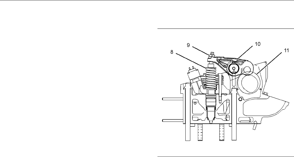
Electronic Unit Injector Mechanism
g01405609
Illustrati
on 7
Electronic unit injector mechanism
(8) E lectronic unit injector
(9) Adjusting nut
(10) Rocker arm assembly
(11) Camshaft lobe
The electro
nic unit injector mechanism provides
the downward for ce tha t is req uire d to pres surize
the fuel in the electronic unit injector pump. The
electronic
unit injector (8) allows fuel to be injecte d
into the combustion chamber with precise timing.
Movement is transmitted from the camshaft lobe
(11) for th
e electronic unit injector through the rocker
arm assembly (10) to the top of the electronic unit
injector. The adjustin g nut (9) allows the injector lash
to be adjus
ted. For the proper setting of the injector
lash, refer to the topic on adjustment of the electronic
unit inje cto r in Testing and Adjusting, “Electronic Unit
Injector
- Adjust”.
Contents Summary of C27 and C32 Generator Set Engines Systems Operation Testing and Adjusting
- Page 1RENR9968-02 July 2007 Systems Operation Testing and Adjusting C27 and C32 Generator Set Engines DWB1-Up (Generator Set) SXC1-Up (Generator Set) MED1-Up (Power Module) MEG1-Up (Power Module) WDR1-Up (Generator Set)�
- Page 2i01658146 Important Safety Information Most accidents that involve product operation, maintenance and repair are caused by failure to observe basic safety rules or precautions. An accident can often be avoided by recognizing potentially hazardous situations before an accident occurs. A person must b
- Page 3RENR9968-02 3 Table of Contents Table of Contents Index Section Index ..................................................................... 65 Systems Operation Section General Information ................................................ 4 Electronic Control System Components ................. 6 Fue
- Page 44 RENR9968-02 Systems Operation Section Systems Operation Section i02411347 General Information SMCS Code: 1000 g01205382 Illustration 1 Typical example (1) Electronic Control Module (ECM) (5) Engine oil filters (8) Flywheel housing (2) Turbocharger (6) Secondary fuel filter and fuel priming (3) Pri
- Page 5RENR9968-02 5 Systems Operation Section Starting the Engine The engine’s ECM will automatically provide the correct amount of fuel in order to start the engine. Do not hold the throttle down while the engine is cranking. If the engine fails to start in twenty seconds, release the starting switch. Al
- Page 66 RENR9968-02 Systems Operation Section i02760232 Electronic Control System Components SMCS Code: 1900 g01205842 Illustration 2 Top view (1) Inlet air temperature sensor (4) Atmospheric pressure sensor (7) Oil pressure sensor (2) Inlet air pressure sensor (5) Secondary engine speed/timing sensor (8)
- Page 7RENR9968-02 7 Systems Operation Section The electronic control system is integrally designed into the engine’s fuel system and the engine’s air inlet and exhaust system in order to electronically control the fuel delivery. The electronic control system provides better timing control and fuel air rat
- Page 88 RENR9968-02 Systems Operation Section As an example, a moving solenoid plunger will Cat ET can be used to program the customer perform work. By performing work, the component specified parameters. The tool is plugged into has functioned in order to regulate the engine. the data link connector. Thi
- Page 9RENR9968-02 9 Systems Operation Section The ECM also monitors all sensor inputs and the ECM provides the correct outputs in addition to acting as a power supply. Also, the ECM ensures the desired engine operation. The ECM is programmed with a selected factory engine rating. The ECM memory contains a
- Page 1010 RENR9968-02 Systems Operation Section i02760777 Fuel System SMCS Code: 1250 g01155662 Illustration 6 (1) Cylinder head (4) Secondary fuel filter and priming pump (7) Primary fuel filter and water separator (2) Unit injector (5) Fuel tank (3) Fuel transfer pump (6) Electronic Control Module (ECM)
- Page 11RENR9968-02 11 Systems Operation Section • Injection duration During engine operation, fuel injectors (2) receive fuel from the low pressure fuel system. The injector • Engine cold mode status pressurizes the fuel to high pressure. The fuel is then injected into the cylinder. The excess fuel is retu
- Page 1212 RENR9968-02 Systems Operation Section • Horsepower Electronic Unit Injector Mechanism • Torque curves • Engine speed (rpm) • Other characteristics The ECM, the personality module, the engine sensors, and the unit injectors work together in order to control the engine. Neither of the four can cont
- Page 13RENR9968-02 13 Systems Operation Section Electronic Unit Injector As the electronic unit injector mechanism transfers the force to the top of the electronic unit injector, spring (12) is compressed and plunger (15) is driven downward. This action displaces fuel through the valve in solenoid valve as
- Page 1414 RENR9968-02 Systems Operation Section i02630349 Air is forced from the aftercooler into inlet manifold (1). The air flow from the inlet port into the cylinders Air Inlet and Exhaust System is controlled by inlet valves. SMCS Code: 1050 g01115385 Illustration 9 (1) Inlet to the engine (2) Aftercoo
- Page 15RENR9968-02 15 Systems Operation Section Turbocharger g01319184 Illustration 12 Turbocharger with wastegate (23) Canister (24) Actuating lever The engine can operate under conditions of low boost (lug). Low boost is a condition that occurs g01319169 when the turbocharger produces less than optimum I
- Page 1616 RENR9968-02 Systems Operation Section Valves And Valve Mechanism g01319198 Illustration 13 Valve system components (25) Valve bridge (26) Rocker arm (27) Camshaft (28) Rotocoil g01319199 (29) Valve spring Illustration 14 (30) Valve guide Components of the gear train (31) Valve (32) Timing mark (3
- Page 17RENR9968-02 17 Systems Operation Section Rotocoils (28) cause the valves to rotate while the engine is running. Valve rotation provides a longer service life. Valve rotation also minimizes carbon deposits on the valves. Adjustable idler gear (34) is designed to provide the required gear backlash bet
- Page 1818 RENR9968-02 Systems Operation Section g01087263 Illustration 15 Lubrication system schematic�
- Page 19RENR9968-02 19 Systems Operation Section (1) Upper rear idler bearing (10) Shaft bearing for the live idler (20) Extension for the oil gallery (2) Oil passage for the rear housing (11) Connecting rod with drilled oil passage (21) Oil filter bypass valve (3) Middle rear idler bearing (12) External oi
- Page 2020 RENR9968-02 Systems Operation Section i02414165 Water pump (9) is located on the right side of the cylinder block. The water pump is gear-driven from Cooling System the front gear group. Coolant can enter the water pump in two places: SMCS Code: 1350 • Inlet at the bottom of the water pump This e
- Page 21RENR9968-02 21 Systems Operation Section Coolant Conditioner (If Equipped) Some conditions of operation can cause pitting. This pitting is caused by corrosion or by cavitation erosion. A corrosion inhibitor is a chemical that provides a reduction in pitting. The addition of a corrosion inhibitor can
- Page 2222 RENR9968-02 Systems Operation Section i02290289 Pistons, Rings And Connecting Basic Engine Rods SMCS Code: 1200 The piston is a one-piece design that consists of a forged steel crown and a skirt. The piston is retained by the piston pin to the small end of the connecting Cylinder Block Assembly r
- Page 23RENR9968-02 23 Systems Operation Section Camshaft Grounding Practices The camshaft has three lobes at each cylinder. Proper grounding for the electrical system is These lobes allow the camshaft to operate the unit necessary for proper engine performance and injector, the exhaust valves, and the inle
- Page 2424 RENR9968-02 Systems Operation Section The alternator design has no need for slip rings or for NOTICE brushes. The only part of this alternator that moves When jump starting an engine, the instructions in the is the rotor assembly. All of the conductors that carry Operation and Maintenance Manual,
- Page 25RENR9968-02 25 Systems Operation Section The solenoid has windings (one set or two sets) around a hollow cylinder or a hollow housing. A plunger that is spring loaded is located within the solenoid housing. The plunger can move forward and backward. When the start switch is closed and electricity is
- Page 2626 RENR9968-02 Systems Operation Section The starting motor rotates the engine flywheel at a rate that is fast enough to start the engine. The starting motor has a solenoid. When the start switch is activated, the solenoid will move the starter pinion in order to engage the pinion and the ring gear
- Page 27RENR9968-02 27 Testing and Adjusting Section Testing and Adjusting 2. Install a 2P-8278 Tube As (SIGHT GAUGE) in the fuel return line. When possible, install the sight Section gauge in a straight section of the fuel line that is at least 304.8 mm (12 inches) long. Do not install the sight gauge near
- Page 2828 RENR9968-02 Testing and Adjusting Section If excessive air is not seen at the inlet to the fuel transfer pump, the air is entering the system after the fuel transfer pump. Proceed to Step 6. If excessive air is seen at the inlet to the fuel transfer pump, air is entering through the suction side
- Page 29RENR9968-02 29 Testing and Adjusting Section i02209818 6. Remove the suspect unit injector and check the unit injector for signs of exposure to coolant. Electronic Unit Injector - Test Exposure to coolant will cause rust to form on the injector. If the unit injector shows signs of SMCS Code: 1290-08
- Page 3030 RENR9968-02 Testing and Adjusting Section g01123281 g01123312 Illustration 23 Illustration 25 Locating Top Center on the left side of engine Using 9S-9082 Engine Turning Tool (1) Timing bolt (1) Timing bolt (2) Timing bolt location (4) 9S-9082 Engine Turning Tool (3) Cover Note: If the flywheel i
- Page 31RENR9968-02 31 Testing and Adjusting Section 1. Determine if water and/or contaminants are i02285479 present in the fuel. Check the water separator (if equipped). If a water separator is not present, Fuel System - Prime proceed to Step 2. Drain the water separator, if necessary. A full fuel tank min
- Page 3232 RENR9968-02 Testing and Adjusting Section Note: There may be a noticeable change in the 7. Crank the engine for 30 seconds. Allow the starter sound of the running engine when the air purge motor to cool for two minutes. screw is tightened. The change in the sound of the engine is normal. 8. Repea
- Page 33RENR9968-02 33 Testing and Adjusting Section 7. Close and tighten the air purge screw. High Fuel Pressure 8. Crank the engine for 30 seconds. Allow the starter Excessive fuel pressure can cause fuel filter gaskets motor to cool for two minutes. to rupture. The following conditions can cause high fue
- Page 3434 RENR9968-02 Testing and Adjusting Section i02227448 Rear Gear Group - Time SMCS Code: 1206-531 g01124671 Illustration 27 Location of fuel pressure tap To check the fuel transfer pump pressure, remove the plug (1) from the fuel filter base. Install the pressure g01114567 Illustration 28 gauge and
- Page 35RENR9968-02 35 Testing and Adjusting Section Air Inlet and Exhaust System Hot engine components can cause injury from burns. Before performing maintenance on the i02310859 engine, allow the engine and the components to cool. Air Inlet and Exhaust System - Inspect SMCS Code: 1050-040 Making contact w
- Page 3636 RENR9968-02 Testing and Adjusting Section Back pressure is the difference in the pressure between the exhaust at the outlet elbow and the atmospheric air. Hot engine components can cause injury from burns. Before performing maintenance on the engine, allow the engine and the components to cool. H
- Page 37RENR9968-02 37 Testing and Adjusting Section 1. Inspect the compressor wheel for damage from a 2. Inspect the turbine wheel for buildup of carbon and foreign object. If there is damage, determine the other foreign material. Inspect the turbine housing source of the foreign object. As required, clean
- Page 3838 RENR9968-02 Testing and Adjusting Section i02227890 Use the following procedure in order to use the 1U-5470 Engine Pressure Group to measure the Inlet Manifold Pressure - Test inlet manifold pressure: SMCS Code: 1058-081 Table 5 Required Tools Part Part Name Quantity Number 1U-5470 Engine Pressur
- Page 39RENR9968-02 39 Testing and Adjusting Section A very high temperature can indicate that too much i02774006 fuel is flowing to the cylinder. A malfunctioning fuel injection nozzle could cause this very high Engine Valve Lash - temperature. Inspect/Adjust Use the 164-3310 Infrared Thermometer to check
- Page 4040 RENR9968-02 Testing and Adjusting Section If the measurement is not within this range adjustment Note: See Testing and Adjusting, “Finding Top Center is necessary. Refer to “Valve Lash Adjustment”. Position for the No. 1 Piston” for further details. 2. With No. 1 piston at the top center position
- Page 41RENR9968-02 41 Testing and Adjusting Section b. Place the appropriate feeler gauge (5) between the inlet rocker arm and the inlet valve bridge. Turn inlet adjustment screw (4) while valve adjustment locknut (3) is being held from turning. Adjust the valve lash until the correct specification is achi
- Page 4242 RENR9968-02 Testing and Adjusting Section Lubrication System i02414081 Engine Oil Pressure - Test SMCS Code: 1304-081 Measuring Engine Oil Pressure Work carefully around an engine that is running. g00296486 Engine parts that are hot, or parts that are moving, Illustration 34 can cause personal in
- Page 43RENR9968-02 43 Testing and Adjusting Section 2. Start the engine. Run the engine with SAE 10W30 Note: A record of engine oil pressure can be used as or SAE 15W40 oil. The information in the engine an indication of possible engine problems or damage. oil pressure graph is invalid for other oil viscos
- Page 4444 RENR9968-02 Testing and Adjusting Section • The oil suction tube has a leak or a restricted inlet 5. The inlet screen of the oil suction tube for the screen. Refer to Step 5. engine oil pump can have a restriction. This restriction will cause cavitation and a loss of • The engine oil pump is faul
- Page 45RENR9968-02 45 Testing and Adjusting Section i01126690 NOTICE Care must be taken to ensure that fluids are contained Excessive Bearing Wear - during performance of inspection, maintenance, test- Inspect ing, adjusting and repair of the product. Be prepared to collect the fluid with suitable containe
- Page 4646 RENR9968-02 Testing and Adjusting Section • Wrong dipstick or guide tube • Sustained operation at light loads Excessive consumption of engine oil can also result if engine oil with the wrong viscosity is used. Engine oil with a thin viscosity can be caused by fuel leakage into the crankcase or by
- Page 47RENR9968-02 47 Testing and Adjusting Section Cooling System 4. Check the fan clutch. A fan clutch that is not turning at the correct speed can cause improper air speed across the radiator core. The lack of i02630833 proper air flow across the radiator core can cause the coolant not to cool to the pr
- Page 4848 RENR9968-02 Testing and Adjusting Section 10. Check for loose drive belts. b. If the measured restriction is higher than the maximum permissible restriction, there is a a. A loose fan drive belt will cause a reduction in restriction in the exhaust system. Repair the the air flow across the radiat
- Page 49RENR9968-02 49 Testing and Adjusting Section This type of system prevents cavitation in the water pump. Cavitation is the forming of low pressure bubbles in liquids that are caused by mechanical Personal injury can result from escaping fluid un- forces. A pressure type cooling system helps to der pr
- Page 5050 RENR9968-02 Testing and Adjusting Section Slowly loosen the pressure cap in order to relieve the pressure out of the cooling system. Then remove the pressure cap. The level of the coolant should not be more than 13 mm (0.5 inch) from the bottom of the filler pipe. If the cooling system is equippe
- Page 51RENR9968-02 51 Testing and Adjusting Section The 9S-8140 Pressurizing Pump is used to pressure 1. After the engine cools, carefully loosen the filler test the radiator’s filler cap. This pressurizing pump cap. Slowly release the pressure from the cooling is also used to pressure test the cooling sys
- Page 5252 RENR9968-02 Testing and Adjusting Section 1. Ensure that the engine is cool. Loosen the filler cap slowly and allow pressure out of the cooling system. Then remove the filler cap from the Personal injury can result from escaping fluid un- radiator. der pressure. 2. Ensure that the coolant level i
- Page 53RENR9968-02 53 Testing and Adjusting Section Start the engine. Run the engine until the temperature i02228472 reaches the desired range according to the test thermometer. If necessary, place a cover over part of Water Pump - Test the radiator in order to cause a restriction of the air flow. The read
- Page 5454 RENR9968-02 Testing and Adjusting Section Basic Engine Refer to Special Instruction, SMHS7606, “Use of 1P-4000 Line Boring Tool Group” for the instructions that are needed to use the tool group. This tool is i02287898 used in order to check the alignment of the main bearing bores. The 1P-3537 Dia
- Page 55RENR9968-02 55 Testing and Adjusting Section The 8T-0455 Liner Projection Tool Group can be used to check the liner projection. Refer to Special Instruction, “Use of the 8T-0455 Liner Projection Tool Group” for more information on the use of the tool. g01388332 Illustration 46 Liner Projection Compo
- Page 5656 RENR9968-02 Testing and Adjusting Section g01086418 Illustration 47�
- Page 57RENR9968-02 57 Testing and Adjusting Section 1. Install a new spacer plate gasket and a clean When the liner projection is correct, put a temporary spacer plate. mark on the liner and the spacer plate. Set the liners aside. 2. Install the cylinder liners in the cylinder block without seals or bands.
- Page 5858 RENR9968-02 Testing and Adjusting Section 3. Turn the flywheel at intervals of 90 degrees and read the dial indicator. 4. Take the measurements at all four points. The difference between the lower measurements and the higher measurements that are performed at all four points must not be more than
- Page 59RENR9968-02 59 Testing and Adjusting Section Face Runout (Axial Eccentricity) of Bore Runout (Radial Eccentricity) the Flywheel Housing of the Flywheel Housing g00285931 g00285934 Illustration 51 Illustration 53 8T-5096 Dial Indicator Gp 8T-5096 Dial Indicator Gp If you use any other method except t
- Page 6060 RENR9968-02 Testing and Adjusting Section 2. While the dial indicator is in the position at location (C) adjust the dial indicator to 0.0 mm (0.00 inch). Push the crankshaft upward against the top of the bearing. Refer to Illustration 55. Write the measurement for bearing clearance on line 1 in c
- Page 61RENR9968-02 61 Testing and Adjusting Section i02031090 NOTICE Vibration Damper - Check Inspect the viscous vibration damper for signs of leak- ing and for signs of damage to the case. Either of SMCS Code: 1205-535 these conditions can cause the weight to contact the case. This contact can affect dam
- Page 6262 RENR9968-02 Testing and Adjusting Section Electrical System i02482495 Battery - Test SMCS Code: 1401-081 Most of the tests of the electrical system can be done on the engine. The wiring insulation must be in good condition. The wire and cable connections must be clean, and both components must be
- Page 63RENR9968-02 63 Testing and Adjusting Section Note: Refer to Operating Manual, SEHS9249, “Use 225-8266 Ammeter Tool Gp of 4C-4911 Battery Load Tester for 6, 8, and 12 Volt Lead Acid Batteries” for detailed instruction on the use of the 4C-4911 Battery Load Tester. Refer to Operating Manual, NEHS0764,
- Page 6464 RENR9968-02 Testing and Adjusting Section 237-5130 Digital Multimeter Gp or 146-4080 Digital Multimeter Gp g00283566 Illustration 61 237-5130 Digital Multimeter Gp or 146-4080 Digital Multimeter Gp The 237-5130 Digital Multimeter Gp and the 146-4080 Digital Multimeter Gp are portable hand-held se
- Page 65RENR9968-02 65 Index Section Index A Engine Oil Pump - Inspect..................................... 45 Engine Valve Lash - Inspect/Adjust ....................... 39 Air in Fuel - Test..................................................... 27 Valve Lash Adjustment ......................................
- Page 6666 RENR9968-02 Index Section L Lubrication System .......................................... 17, 42 M Main Bearings - Inspect......................................... 54 P Piston Ring Groove - Inspect................................. 54 R Rear Gear Group - Time.......................................
- Page 67RENR9968-02 67 Index Section�
- Page 68©2007 Caterpillar All Rights Reserved Printed in U.S.A.