247, 257, 267, 277 and 287 Multi Terrain Loaders Operation and Maintenance Manual Page 141
Operation and Maintenance Manual
SEBU7494-06 141
Maintenance Section
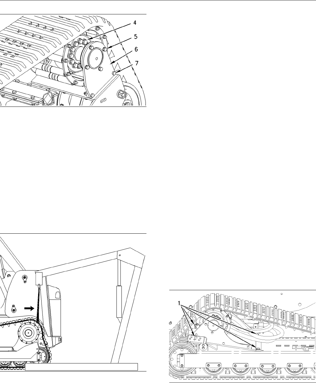
Track (Rubber) - Remove/Replace
g00954090
Illustration 190
8. Remove the two bolts and the locknuts (7).
Remove the four bolts and lockwashers (5).
Remove the support plate for the drive sprocket
(6).
Note: When you reinstall the bolts (6) tighten the bolts
to the following torque 120 ± 20 N·m (89 ± 15 lb ft).
When you reinstall the bolts (7) tighten the bolts to
the following torque 105 ± 20 N·m (77 ± 15 lb ft).
9. Remove the twelve bolts (4) that retain the drive
sprocket to the drive motor.
Note: When you reinstall the bolts (4) tighten the bolts
to the following torque 270 ± 40 N·m (199 ± 30 lb ft).
g00954096
Illustration 191
10. Use a lifting device that is suitable in order to lift
the track. Lift the track in order to remove the drive
sprocket. It may be necessary to insert a chock in
front of the rear idler in order to prevent the track
from spinning as you lift the track.
11. Remove the driv
esprocket.
12. Remove the lifting device from the track. The
lifting devic
e is not required for removing the track
from the machine.
13. Grasp the trac
k on top of the drive sprocket. Pull
the top of the track upward and pull the track to
the outside. Slide the track past the bogies. Lift
the track off
the front idlers.
Installing t
he Track 267 and 277
1. Follow the steps in reverse order in order to
replace the t
rack.
2. Tighten the track to the proper tension. Refer
to Operation
and Maintenance Manual, “Track
(Rubber) - Inspect/Adjust”.
Removing the Track 287
1. Position th
e machine on firm, level ground.
2. Remove any work tool that is attached to the quick
coupler.
3. Raise the loader arms and install the brace
for the load
er lift arm. Refer to Operation and
Maintenance Manual, “Loader Lift Arm Brace
Operation”.
4. Use an appropriate floor jack in order to lift the
machine off the ground. Use appropriate jack
stands in o
rder to block up the machine.
5. Detension the track. Refer to Operation
and Mainte
nance Manual, “Track (Rubber) -
Inspect/Adjust”.
g00954340
Illustration 192
6. Remove the four bolts (1) that secure the drive
frame. The two rear bolts are secured with nuts.
Contents Summary of 247, 257, 267, 277 and 287 Multi Terrain Loaders Operation and Maintenance Manual
- Page 1SEBU7494-06 December 2005 Operation and Maintenance Manual 247, 257, 267, 277 and 287 Multi Terrain Loaders CNC1-Up (Machine) CAT00277CCNC01411 CML1-Up (Machine) CMM1-Up (Machine) CMP1-Up (Machine) CNY1-Up (Machine)�
- Page 2i01658146 Important Safety Information Most accidents that involve product operation, maintenance and repair are caused by failure to observe basic safety rules or precautions. An accident can often be avoided by recognizing potentially hazardous situations before an accident occurs. A person must b
- Page 3SEBU7494-06 3 Table of Contents Table of Contents Engine Starting (Alternate Methods) ..................... 86 Maintenance Section Foreword ................................................................. 4 Maintenance Access ............................................. 88 Safety Section Lubricant
- Page 44 SEBU7494-06 Foreword Foreword Maintenance The maintenance section is a guide to equipment Literature Information care. The Maintenance Interval Schedule (MIS) lists the items to be maintained at a specific service This manual should be stored in the operator’s interval. Items without specific inte
- Page 5SEBU7494-06 5 Foreword It is prohibited for any person engaged in the 3. Check Character (character 9) business of repairing, servicing, selling, leasing, or trading engines or machines to remove, alter, or 4. Machine Indicator Section (MIS) or Product render inoperative any emission related device
- Page 66 SEBU7494-06 Safety Section Safety Messages Safety Section i02114035 Safety Messages SMCS Code: 7000; 7405 g01005229 Illustration 2 Typical Example�
- Page 7SEBU7494-06 7 Safety Section Safety Messages g01005251 Illustration 3�
- Page 88 SEBU7494-06 Safety Section Safety Messages Typical Example�
- Page 9SEBU7494-06 9 Safety Section Safety Messages g01076981 Illustration 4�
- Page 1010 SEBU7494-06 Safety Section Safety Messages There are several specific safety messages on this Do Not Operate (1) machine. The exact location of the hazards and the description of the hazards are reviewed in this This warning message is located inside the cab on section. Please become familiarized
- Page 11SEBU7494-06 11 Safety Section Safety Messages Loader Crushing (2) Carrying a Load (3) This message is located below the operator seat. This warning message is located below the operator seat. g00943101 g00943103 Keep out of this area Carry load low. Loader lift arm brace must be in place when work-
- Page 1212 SEBU7494-06 Safety Section Safety Messages Never Permit Riders (4) Stay Inside Operator Station (5) This warning message is located below the operator This warning message is located below the operator seat. seat. g00943118 g00943119 Never permit riders. Keep your body inside operator station whi
- Page 13SEBU7494-06 13 Safety Section Safety Messages Mounting and Dismounting (6) Cab Support (7) This warning message is located below the operator This warning message is located on the left side of seat. the machine near the cab support lever. This warning message is also located inside the cab on the l
- Page 1414 SEBU7494-06 Safety Section Safety Messages Battery (8) Batteries (9) This warning message is located on the battery. This warning message is located on the inside of the engine access door. g00943142 DANGER/POISON Shield eyes, Explosive gases. Can cause blind- ness or injury. g00943143 No sparks,
- Page 15SEBU7494-06 15 Safety Section Safety Messages Work Tool Coupler (11) Falling Object Protective Structure This warning message is located on the coupler (12) assembly. This warning message is located on the right side of the FOPS. g00943146 Do not operate machine without confirmation that coupler pin
- Page 1616 SEBU7494-06 Safety Section Safety Messages Work Tool Coupler (13) Machine Operation in Cold Weather This warning message is located inside the cab near (14) the hydraulic quick coupler control. This warning message is located inside the cab on the right side. g00943149 g00943150 Improper Attachme
- Page 17SEBU7494-06 17 Safety Section Safety Messages Brace for the Loader Lift Arms (15) Pressurized System (17) This warning message is located on the brace for the This warning message is located below the radiator loader lift arms. The illustration may vary depending cap. on the machine that is being se
- Page 1818 SEBU7494-06 Safety Section Safety Messages Rollover Protective Structure/ Crush Point (19) Falling Object Protective Structure The warning messages that are shown are used (18) on the 257 Multi Terrain Loaders and the 277 Multi Terrain Loaders. The messages are located near the This warning messa
- Page 19SEBU7494-06 19 Safety Section Safety Messages Industrial Grapple Bucket (21) Industrial Grapple Fork (23) These warning messages are located on top of the These warning messages are located on the guards guards for the grapple cylinders. for the grapple cylinders. g00943160 g00943172 No clearance fo
- Page 2020 SEBU7494-06 Safety Section Safety Messages Angle Blade (25) Utility Grapple Fork (27) These warning messages are located on the back These warning messages are located on top of the side of the blade. fork carriage. g00943177 g00943179 No clearance for person in this area during oper- No clearanc
- Page 21SEBU7494-06 21 Safety Section Safety Messages Dozer Blade (29) Dozer Blade (31) These warning messages are located on the back This warning message is located on top of the dozer side of the blade. blade. g01039066 g00946617 No clearance for person in this area during oper- Falling Hazard - Area may
- Page 2222 SEBU7494-06 Safety Section General Hazard Information i02443908 Keep the equipment free from foreign material. Remove debris, oil, tools, and other items from the General Hazard Information deck, from walkways, and from steps. SMCS Code: 7000 Secure all loose items such as lunch boxes, tools, and
- Page 23SEBU7494-06 23 Safety Section General Hazard Information Trapped Pressure • Tools that are suitable for collecting fluids and equipment that is suitable for collecting fluids Pressure can be trapped in a hydraulic system. Releasing trapped pressure can cause sudden • Tools that are suitable for cont
- Page 2424 SEBU7494-06 Safety Section Crushing Prevention and Cutting Prevention • Use exhaust ventilation on permanent machining Unless you are instructed otherwise, never attempt jobs. adjustments while the machine is moving or while the engine is running. • Wear an approved respirator if there is no othe
- Page 25SEBU7494-06 25 Safety Section Fire Prevention and Explosion Prevention Check the coolant level only after the engine has Flammable fluids that are leaking or spilled onto hot been stopped. surfaces or onto electrical components can cause a fire. Fire may cause personal injury and property Ensure tha
- Page 2626 SEBU7494-06 Safety Section Fire Prevention and Explosion Prevention Improper jumper cable connections can cause an explosion that can result in injury. Refer to the Operation Section of this manual for specific instructions. Do not charge a frozen battery. This may cause an explosion. Fire Exting
- Page 27SEBU7494-06 27 Safety Section Fire Extinguisher Location • Wires are exposed. • Dismount the machine. • Outer coverings are ballooning. If you are in the operator’s station during an electrical storm, stay in the operator’s station. If you are on the • Flexible part of the hoses are kinked. ground d
- Page 2828 SEBU7494-06 Safety Section Before Operation i01545253 Carry work tools low. Lower the lift arms fully. Tilt back the work tool in order to keep the work tool off Before Operation of the ground. Do not go close to the edge of a cliff, an excavation, or an overhang. SMCS Code: 7000 If the machine b
- Page 29SEBU7494-06 29 Safety Section Parking Keep all windows and doors closed on the host i01329161 machine. Always wear protective glasses. Always wear the protective equipment that is recommended Equipment Lowering with in the work tool’s operation manual. Wear any other protective equipment that is req
- Page 3030 SEBU7494-06 Safety Section Guards The interior sound power level is 84 dB(A) for the 277 Rollover Protective Structure and 287 machines. The interior sound power level is 89 dB(A) for the 247, 257 and 267 machines. The (ROPS), Falling Object Protective exterior sound power level is 106 dB(A). The
- Page 31SEBU7494-06 31 Safety Section Guards • Demolition applications • Rock quarries • Forestry products Additional guards may be required for specific applications or work tools. The Operation and Maintenance Manual for your machine or your work tool will provide specific requirements for the guards. Con
- Page 3232 SEBU7494-06 Product Information Section General Information Product Information The corresponding dump clearance is given for each bucket at maximum lift height and at a 40 degree Section dump angle. The reach is given for each bucket at maximum lift height and at a 40 degree dump angle. Clearanc
- Page 33SEBU7494-06 33 Product Information Section General Information Table 1 General Purpose Buckets Part Number 165-6152 165-6153 165-6154 199-7720 1524 mm 1676 mm 1828 mm 1981 mm Width (60 inch) (66 inch) (72 inch) (78 inch) 0.48 m3 Rated Volume 0.36 m3 (0.40 yd3) 0.40 m3 (0.44 yd3) 0.44 m3 (0.48 yd3) (
- Page 3434 SEBU7494-06 Product Information Section General Information Table 2 Multipurpose Buckets Part Number 154-5004 154-5008 154-5010 199-8320 Width 1524 mm 1676 mm 1829 mm 1981 mm (78 inch) (60 inch) (66 inch) (72 inch) Rated Volume 0.30 m3 0.34 m3 (0.37 yd3) 0.37 m3 (0.48 yd3) 0.40 m3 (0.44 yd3) (0.3
- Page 35SEBU7494-06 35 Product Information Section General Information Table 3 Dirt Buckets Part Number 165-6155 165-6156 165-6157 188-3526 Width 1372 mm 1524 mm 1676 mm (66 inch) 1829 mm (54 inch) (60 inch) (72 inch) Rated Volume 30 m3 (33 yd3) 0.34 m3 0.37 m3 (0.40 yd3) 0.41 m3 (0.37 yd3) (0.45 yd3) Bucke
- Page 3636 SEBU7494-06 Product Information Section General Information Table 4 Utility Buckets Part Number 165-8835 165-8746 165-8778 Width 1524 mm (60 inch) 1676 mm (66 inch) 1829 mm (72 inch) Rated Volume 0.42 m (0.46 yd ) 3 3 0.47 m (0.51 yd ) 3 3 0.51 m3 (0.66 yd3) Bucket Weight 211 kg (465 lb) 226 kg (
- Page 37SEBU7494-06 37 Product Information Section General Information Table 5 Light Material Buckets Part Number 164-7416 167-7417 Width 1829 mm (72 inch) 1981 mm (78 inch) Rated Volume 0.69 m (0.90 yd ) 3 3 0.75 m3 (0.98 yd3) Bucket Weight 257 kg (566 lb) 272 kg (600 lb) Models 247 R.O.C 644 kg (1419 lb)
- Page 3838 SEBU7494-06 Product Information Section General Information Table 6 Industrial Grapple Buckets(1) Part Number 157-7223 157-7224 157-7225 Width 1524 mm (60 inch) 1676 mm (66 inch) 1829 mm (72 inch) Bucket Weight 398 kg (877 lb) 413 kg (910 lb) 427 kg (941 lb) Models 247 R.O.C 588 kg (1296 lb) 582
- Page 39SEBU7494-06 39 Product Information Section General Information Table 7 Utility Grapple Buckets (1) Part Number 165-8729 165-8730 Width 1676 mm (66 inch) 1829 mm (72 inch) Bucket Weight 330 kg (728 lb) 344 kg (758 lb) Models 247 R.O.C 583 kg (1285 lb) 578 kg (1274 lb) 35% R.O.C 833 kg (1836 lb) 826 k
- Page 4040 SEBU7494-06 Product Information Section General Information g00777498 Illustration 15 Dimension (A) represents the maximum fork height. Dimension (B) represents the load center. Dimension (C) represents the reach. Dimension (D) represents the fork tine length. The maximum fork height (ground to t
- Page 41SEBU7494-06 41 Product Information Section General Information Table 8 Rated Operating Load with a Pallet Fork Part Number 151-5134 149-1412 161-2437 Weight 184 kg (406 lb) 194 kg (428 lb) 203 kg (448 lb) (B) 455 mm (18 inch) 535 mm (21 inch) 610 mm (24 inch) (D) 910 mm (36 inch) 1070 mm (42 inch) 1
- Page 4242 SEBU7494-06 Product Information Section General Information Table 9 Rated Operating Load with a Utility Fork Part Number 165-8732 165-8737 Weight 195 kg (430 lb) 217 kg (478 lb) Width 1676 mm (66 inch) 1829 mm (72 inch) (B) 314 mm (12 inch) 314 mm (12 inch) Models 247 R.O.C 420 kg (925 lb) 414 kg
- Page 43SEBU7494-06 43 Product Information Section General Information g00668844 Illustration 16 Lifting point 1 (1) Lifting point 2 (2) g00779834 Illustration 17 Dimension (A) represents the clearance at the full down position from Lifting Point 2. Dimension (a) represents the clearance at the full down po
- Page 4444 SEBU7494-06 Product Information Section General Information Table 10 Models Lifting Point 1 (1) Lifting Point 2 (2) 247 R.O.C 543 kg (1197 lb) 447 kg (985 lb) Clearance at Full Down 1119 mm (3.7 ft) 1614 mm (5.3 ft) Clearance at Maximum 3868 mm (12.7 ft) 4312 mm (14.1 ft) Height Minimum Reach 653
- Page 45SEBU7494-06 45 Product Information Section General Information Table 11 247 257 267 277 287 Maximum 3002 kg (6618 lb) 3439 kg (7582 lb) 4089 kg (9015 lb) 4106 kg (9052 lb) 4412 kg (9727 lb) Machine Weight Overall 2701 mm 2701 mm 2923 mm 2923 mm 2901 mm Length (106 inch) (106 inch) (115 inch) (115 in
- Page 4646 SEBU7494-06 Product Information Section Identification Information Identification Information • Model ______________________________________________________ • Power (kW) _______________________________________________ i01946856 • Weight (kg) _______________________________________________ Plate L
- Page 47SEBU7494-06 47 Product Information Section Identification Information g00776690 Illustration 21�
- Page 4848 SEBU7494-06 Operation Section Before Operation Operation Section i01946878 Daily Inspection Before Operation SMCS Code: 1000; 7000 NOTICE i02189821 Accumulated grease and oil on a machine is a fire haz- ard. Remove this debris with steam cleaning or high Mounting and Dismounting pressure water, a
- Page 49SEBU7494-06 49 Operation Section Before Operation • Operation and Maintenance Manual, “Quick Coupler - Inpsect/Adjust” • Operation and Maintenance Manual, “Work Tool Mounting Bracket - Inspect” • Operation and Maintenance Manual, “Backup Alarm - Test” Refer to the Maintenance Section for the detaile
- Page 5050 SEBU7494-06 Operation Section Before Operation 247 Service Interval Chart g00892512 Illustration 23�
- Page 51SEBU7494-06 51 Operation Section Before Operation 257 and 287 Service Interval Chart g00892465 Illustration 24�
- Page 5252 SEBU7494-06 Operation Section Before Operation 267 and 277 Service Interval Chart g00785614 Illustration 25 Service Intervals Engine air filter secondary element – Engine air filter primary element – Clean Replace the secondary air filter element the primary air filter element or replace with eve
- Page 53SEBU7494-06 53 Operation Section Before Operation Hydraulic oil level check – Check the Cooling system coolant – Change the hydraulic oil level at the sight gauge after ELC (Extended Life Coolant) after every every ten service hours or at the end of 6000 hours or every 4 years. each day. Bogie oil l
- Page 5454 SEBU7494-06 Operation Section Machine Operation Machine Operation i01822242 Seat Belt i01850883 SMCS Code: 7327 Alternate Exit Note: This machine was equipped with a seat belt SMCS Code: 7000 when the machine was shipped from Caterpillar. At the time of installation, the seat belt and the instruc
- Page 55SEBU7494-06 55 Operation Section Machine Operation 2. To remove the slack in outer loop (1), rotate buckle Releasing The Seat Belt (2). This will free the lock bar. This permits the seat belt to move through the buckle. 3. Remove the slack from the outer belt loop by pulling on the buckle. 4. Loosen
- Page 5656 SEBU7494-06 Operation Section Machine Operation Releasing The Seat Belt g00039113 Illustration 34 Push the release button on the buckle in order to release the seat belt. The seat belt will automatically retract into the retractor. Extension of the Seat Belt When using retractable seat belts, do
- Page 57SEBU7494-06 57 Operation Section Machine Operation g01005547 Illustration 35 (1) Interlock Control (12) Turn Signals (23) Auxiliary Hydraulic Control (2) Seat Adjustment (13) Hazard Flashers (24) Auxiliary Electrical Control (3) Engine Start Switch (14) Roading Lights (25) Plugged (4) Glow Plug Star
- Page 5858 SEBU7494-06 Operation Section Machine Operation Interlock Control (1) Parking Brake Control (5) Interlock Control – Move the armrest to the Parking Brake Control – Press on the RAISED position in order to lock out the hydraulic right side of the switch in order to engage controls. or disengage th
- Page 59SEBU7494-06 59 Operation Section Machine Operation Speed and Direction Control (8) When you release the joystick from any position, the joystick will return to the HOLD position (9). The machine will stop moving when the joystick is in the HOLD position. Work Tool Control (9) g00741590 Illustration
- Page 6060 SEBU7494-06 Operation Section Machine Operation Work Tool Coupler Control (10) Roading Lights (14) Roading Lights (If Equipped) – Move the switch to the middle position in order to turn on the control panel lights and position Improper attachment of work tools could result in lights. Press on the
- Page 61SEBU7494-06 61 Operation Section Machine Operation Service Hour Meter (19) Service Hour Meter – The service hour meter should be used to determine service hour maintenance intervals. Fuel Level Gauge (20) Fuel Level Gauge – The needle in the yellow range indicates low fuel. Window Wiper and Window W
- Page 6262 SEBU7494-06 Operation Section Machine Operation Auxiliary Electrical Control (If Interlock Override (If Equipped) – The Equipped) – The auxiliary electrical control interlock override function allows the supplies continuous electrical power to the auxiliary hydraulic circuits to function with ele
- Page 63SEBU7494-06 63 Operation Section Machine Operation Fourth Function Control (If Equipped) – The Basic Operation fourth function control provides electrical power in order to control a three-position diverter valve that is MSS may be programmed to read a standard located on some work tools. Press the
- Page 6464 SEBU7494-06 Operation Section Machine Operation i01635456 Seat and Armrest (5) – The alert indicator Alert Indicators will light when the armrest is in the RAISED position. The alert indicator will light when SMCS Code: 7450; 7451 the operator gets out of the operator seat. The alert indicator sh
- Page 65SEBU7494-06 65 Operation Section Engine Starting Engine Starting 3. Move the governor control lever or the accelerator pedal to half throttle. i02404494 4. Turn the engine start switch key to the START position in order to start the engine. Release the Engine Starting key after the engine has starte
- Page 6666 SEBU7494-06 Operation Section Operation Operation i02121219 Operation Information SMCS Code: 7000 General Information 1. Adjust the operator’s seat. 2. Fasten the seat belt. 3. Lower the armrest. 4. Start the engine and allow the machine to warm up. Refer to Operation and Maintenance Manual, “Eng
- Page 67SEBU7494-06 67 Operation Section Operation NOTICE The use of this machine in certain applications can cause premature failure of the rubber tracks and rub- ber wheels. Applications that may cause premature failure of the rubber tracks and rubber wheels include: use in rocky terrain, use in gravel, u
- Page 6868 SEBU7494-06 Operation Section Operation Operating on a Transition Track Guides g00929633 Illustration 50 Track Guides are available for the 267 and 277 machines only. The use of track guides on the 267 and 277 machines will minimize the risk of derailing the tracks on a transition or a slope. Tra
- Page 69SEBU7494-06 69 Operation Section Operation i01935351 2. If the machine is equipped with a manual coupler, ensure that the levers for the coupler are in Work Tool Coupler Operation the DISENGAGED position. If the machine is equipped with a hydraulic quick coupler refer to SMCS Code: 6129; 7000 Operat
- Page 7070 SEBU7494-06 Operation Section Operation Note: If you are installing a material handling arm a. Route the hydraulic hoses through the hose that is not equipped with the optional center step, guide on the machine in order to prevent do not exit the machine. A second person needs to damage to the ho
- Page 71SEBU7494-06 71 Operation Section Operation 16. Visually ensure that both coupler pins are 3. Rack back the work tool until the work tool is extending out of the holes in the work tool slightly off the ground. mounting bracket. 4. Turn the engine start switch key to the OFF 17. Use the following proc
- Page 7272 SEBU7494-06 Operation Section Operation 13. If the machine is equipped with a manual coupler, 3. Press each side of the auxiliary hydraulic control ensure that the levers for the coupler are in switch (A1 and A2) for one to two seconds in order the DISENGAGED position. If the machine is to releas
- Page 73SEBU7494-06 73 Operation Section Operation Inspect the material handling arm and the 5. Keep the loader arms in the fully lowered position. attachments for wear and damage. Ensure that the Slowly position the material handling arm until load is properly attached to the material handling arm either l
- Page 7474 SEBU7494-06 Operation Section Operation Note: Do not move the load when you are securing Attaching the Load the load. Do not pull the load toward the material handling arm when you are securing the load to the 1. Verify that the load does not exceed the weight tie-down points. limit. Refer to the
- Page 75SEBU7494-06 75 Operation Section Operation 9. Lower the load to the ground. 10. Stop the engine. Exit the machine. Note: Make sure that the load is stable. 11. Remove the load from the hook. 12. Keep all personnel out of the work area. 13. Enter the machine. Start the engine. 14. Disengage the parki
- Page 7676 SEBU7494-06 Operation Section Operation While you operate the machine and the work tool slowly in an open area, check for proper operation of all controls and all protective devices on the machine and the work tool. g00955964 Illustration 64 The “type 2” pin that is in the unlocked position (1) a
- Page 77SEBU7494-06 77 Operation Section Operation Table 13 OPERATION OF CATERPILLAR SIMPLE HYDROMECHANICAL WORK TOOLS Position Position of of Fourth Auxiliary Work Tool Function Hydraulic Results Control Control C2 C1 A1 A2 X The bucket will close. Multipurpose Bucket N/A(1) X The bucket will open. Industr
- Page 7878 SEBU7494-06 Operation Section Operation (Table 14, contd) OPERATION OF CATERPILLAR COMPLEX HYDROMECHANICAL WORK TOOLS Position Position of of Fourth Auxiliary Work Tool Function Hydraulic Results Control Control C2 C1 A1 A2 If the sideshift control is in the PLANER position, the drum rotates cloc
- Page 79SEBU7494-06 79 Operation Section Parking Parking i01871966 Stopping the Engine if an i01992184 Electrical Malfunction Occurs Stopping the Engine SMCS Code: 1000; 7000 SMCS Code: 1000; 7000 1. Lower the work tool to the ground. NOTICE 2. Raise the armrest. Unfasten the seat belt. Exit Stopping the en
- Page 8080 SEBU7494-06 Operation Section Parking Before lowering any equipment with the engine Do not go under the raised lift arm without the brace stopped, clear the area around the equipment of all for the loader lift arm in the LOCKED position. Use personnel. The procedure will vary with the type of the
- Page 81SEBU7494-06 81 Operation Section Parking To store machines in ambient temperatures between −20 °C (−4.0 °F) to 43 °C (109.4 °F), refer to Special Instructions, SEHS9031, “Storage Procedure for Caterpillar Products”. To store machines in ambient temperatures between −32 °C (−26 °F) and −21 °C (−6 °F)
- Page 8282 SEBU7494-06 Operation Section Transportation Information Transportation Information 2. When you use loading ramps, make sure that the loading ramps have adequate length, adequate width, and adequate strength. In addition, make i01632001 sure that the surface of the loading ramps are clean. This w
- Page 83SEBU7494-06 83 Operation Section Transportation Information 13. Cover the exhaust opening when the machine The machine can be lifted with a bucket that is not has cooled down. hydraulic. The machine can be lifted with a pallet fork that is not hydraulic. All other work tools must Unloading the Machi
- Page 8484 SEBU7494-06 Operation Section Transportation Information Tying Down the Machine g01019061 Illustration 71 The two front eyes (1) are provided for tie-downs. g01019063 Illustration 72 The two rear eyes (2) are provided for tie-downs. Install tie-downs at all four locations. Place chocks in front o
- Page 85SEBU7494-06 85 Operation Section Towing Information Towing Information • Attach the line to the towing eyes. Two towing eyes (1) are located on the front of the machine and two towing eyes (2) are located on the rear of the i01821491 machine. Do not attach the line to any other point on the machine.
- Page 8686 SEBU7494-06 Operation Section Engine Starting (Alternate Methods) Engine Starting (Alternate NOTICE Methods) To prevent damage to engine bearings and to elec- trical circuits when you jump start a machine, do not allow the stalled machine to touch the machine that is i02065056 used as the electri
- Page 87SEBU7494-06 87 Operation Section Engine Starting (Alternate Methods) 8. Connect the other positive end of the jump start cable to the positive cable terminal of the electrical source. 9. Connect one negative end of the jump start cable to the negative cable terminal of the electrical source. 10. Con
- Page 8888 SEBU7494-06 Maintenance Section Maintenance Access Maintenance Section Maintenance Access i01871110 Access Doors and Covers SMCS Code: 7273-572; 7273-573 Engine Access Door g00953140 The engine access door is located on the back of Illustration 78 the machine. 3. In order to close the engine acce
- Page 89SEBU7494-06 89 Maintenance Section Maintenance Access g00952728 Illustration 81 The cab support lever is in the ENGAGED position. 7. Make sure that the cab support lever is in the ENGAGED position. Illustration 79 g00930086 Tilting the Cab Downward 5. Remove the two front bolts for the ROPS. Note: M
- Page 9090 SEBU7494-06 Maintenance Section Maintenance Access Table 15 (Table 15, contd) Spring Factoring Table OPTION 3 The right side gas strut 7-9 153-2682 Part Number Name Factor The left side gas strut 142-9310 Seat and Mounting 0 153-2683 (Static) OPTION 4 The right side gas strut 10+ 142-9305 Seat an
- Page 91SEBU7494-06 91 Maintenance Section Maintenance Access 5. Raise the lift arms until the brace falls onto the cylinder rod. Slowly lower the lift arms until the brace stops movement. g00952609 Illustration 86 4. Slowly raise the loader lift arms until the lever Illustration 84 g00952492 engages the re
- Page 9292 SEBU7494-06 Maintenance Section Maintenance Access g00952659 g00941929 Illustration 88 Illustration 89 4. The second person should then install the brace 2. Pull the release lever for the radiator latch. Tilt the over the rod of one of the lift cylinders. radiator upward. 5. Lower the loader arms
- Page 93SEBU7494-06 93 Maintenance Section Maintenance Access g00955515 Illustration 91 2. Remove the retaining pin from the radiator guard. Tilt the radiator guard upward. 3. In order to tilt the radiator guard downward, pull down on the radiator guard and install the retaining pin.�
- Page 9494 SEBU7494-06 Maintenance Section Lubricant Viscosities and Refill Capacities Lubricant Viscosities and Refill Capacities i02410257 Lubricant Viscosities SMCS Code: 7581 The proper oil viscosity grade is determined by the minimum outside temperature when the machine is started. The proper oil visco
- Page 95SEBU7494-06 95 Maintenance Section Lubricant Viscosities and Refill Capacities (Table 16, contd) Lubricant Viscosities for Ambient Temperatures Oil °C °F Compartment or System Oil Type and Classification Viscosities Min Max Min Max SAE 0W-20 −40 40 −40 104 SAE 0W-30 −40 40 −40 104 SAE 0W-40 −40 40 −
- Page 9696 SEBU7494-06 Maintenance Section Lubricant Viscosities and Refill Capacities i02098494 i01822901 Capacities (Refill) S·O·S Information SMCS Code: 7560 SMCS Code: 1000; 7000; 7542-008 Table 17 S·O·S Services is a highly recommended process Approximate Refill Capacities for Caterpillar customers to
- Page 97SEBU7494-06 97 Maintenance Section Maintenance Support Maintenance Support i02000840 Welding on Machines and Engines with Electronic Controls SMCS Code: 1000; 7000 Proper welding procedures are necessary in order to avoid damage to the electronic controls and to the bearings. When possible, remove t
- Page 9898 SEBU7494-06 Maintenance Section Maintenance Interval Schedule i02418872 Hydraulic System Oil Level - Check ................... 126 Lift Arm and Cylinder Linkage - Lubricate ........... 126 Maintenance Interval Schedule Quick Coupler - Inspect ...................................... 128 Radiator Co
- Page 99SEBU7494-06 99 Maintenance Section Maintenance Interval Schedule Every 3000 Service Hours or 2 Years Cooling System Coolant Extender (ELC) - Add ... 110 Cooling System Water Temperature Regulator - Replace .............................................................. 111 Every 3 Years After Date of
- Page 100100 SEBU7494-06 Maintenance Section Axle Bearings - Lubricate i01989568 1. Get into the operator’s seat. Fasten the seat belt and pull the armrest downward. Axle Bearings - Lubricate 2. Start the engine. SMCS Code: 3282-086-BD 3. Disengage the parking brake. S/N: CML1-Up S/N: CMM1-Up 4. Move the spe
- Page 101SEBU7494-06 101 Maintenance Section Belts - Inspect/Adjust/Replace 7. Install the engine start switch key. Repeat the process for the positive battery cable. i01851684 Belts - Inspect/Adjust/Replace SMCS Code: 1357-025; 1357-040; 1357-510 If a new belt is installed, check the belt adjustment after 3
- Page 102102 SEBU7494-06 Maintenance Section Bogie and Idler - Inspect/Replace i01988720 Bogie and Idler - Inspect/Replace SMCS Code: 4159-040; 4159-510; 4192-040; 4192-510 Clean the undercarriage before inspecting the bogies and the idlers. Inspect the bogies and idlers for damage and wear. Note: Minor dama
- Page 103SEBU7494-06 103 Maintenance Section Bogie and Idler - Inspect/Replace Replacement for the 247B and 257B g01029962 Illustration 97 1. Remove the track. Refer to Operation and Maintenance Manual, “Track (Rubber) - Remove/Replace”. 2. Remove the retaining ring (1) and the dust cap (2). 3. Remove the nu
- Page 104104 SEBU7494-06 Maintenance Section Bogie and Idler - Inspect/Replace Replacement for the 267B and 277B g00955323 Illustration 98 1. Remove the track. Refer to Operation and Note: When you reinstall the four bolts, tighten the Maintenance Manual, “Track (Rubber) - bolts to the following torque 95 ±
- Page 105SEBU7494-06 105 Maintenance Section Bogie and Idler Oil Level - Check Replacement for the 287B g01030397 Illustration 99 1. In order to remove a bogie group, remove the i02429710 four bolts, lockwashers, locknuts (1) and plates. In order to remove an idler group, remove the four Bogie and Idler Oil
- Page 106106 SEBU7494-06 Maintenance Section Bucket Cutting Edges - Inspect/Replace i01743875 Bucket Cutting Edges - Personal injury or death can result from servicing the track. Inspect/Replace The machine must be on a hard, level surface be- SMCS Code: 6801-040; 6801-510 fore the track is removed or person
- Page 107SEBU7494-06 107 Maintenance Section Cab Air Filter - Clean/Replace 4. Clean the mounting surface. Recirculation Filter 5. Replace the bucket tips. 6. Install the bolts. 7. Remove the blocks that are under the bucket. 8. After a few hours of operation, check the bolts for proper torque. i01962545 Cab
- Page 108108 SEBU7494-06 Maintenance Section Cooling System Coolant (ELC) - Change • (8) Cold Start and Hydraulic Filter • (9) Left Tail Lamp • (10) Right Tail Lamp • (11) Auxiliary tools • (12) Fourth Function • (13) Heater • (14) Horn g00895355 • (15) Miscellaneous Power Illustration 103 • (16) Key Switch
- Page 109SEBU7494-06 109 Maintenance Section Cooling System Coolant (ELC) - Change NOTICE Mixing ELC with other products will reduce the effec- tiveness of the coolant. This could result in damage to cooling system compo- nents. If Caterpillar products are not available and com- mercial products must be used
- Page 110110 SEBU7494-06 Maintenance Section Cooling System Coolant Extender (ELC) - Add g00956179 g00956151 Illustration 108 Illustration 109 9. Maintain the coolant level in the sight gauge. The 3. Slowly loosen the radiator cap in order to relieve sight gauge is located on the right side of the system pre
- Page 111SEBU7494-06 111 Maintenance Section Cooling System Level - Check i01874850 4. If you need to add coolant to the radiator, the radiator cap is located on the upper left corner of Cooling System Level - Check the radiator. Remove the radiator cap slowly in order to relieve system pressure. SMCS Code:
- Page 112112 SEBU7494-06 Maintenance Section Engine Air Filter Primary Element - Clean/Replace 1. Open the engine access door. Refer to Operation and Maintenance Manual, “Access Doors and NOTICE Covers”. Caterpillar recommends certified air filter cleaning ser- vices that are available at Caterpillar dealers
- Page 113SEBU7494-06 113 Maintenance Section Engine Air Filter Secondary Element - Replace g00101864 Illustration 116 1. Remove the air cleaner housing cover (1). 2. Remove the primary filter element (2). 3. Install a clean filter element and install the cover. g00891467 Illustration 117 4. Reset the engine
- Page 114114 SEBU7494-06 Maintenance Section Engine Air Filter Service Indicator - Inspect 4. Cover the air inlet opening. Clean the inside of the air cleaner housing. 5. Inspect the gasket between the air inlet pipe and the air cleaner housing. Replace the gasket if the gasket is damaged. 6. Uncover the air
- Page 115SEBU7494-06 115 Maintenance Section Engine Compartment - Clean i01978979 i01819955 Engine Compartment - Clean Engine Crankcase Breather SMCS Code: 1000-070 (Closed Circuit) - Replace SMCS Code: 1317-510 Inspect the engine compartment for dirt buildup or debris. Remove any dirt or debris from the eng
- Page 116116 SEBU7494-06 Maintenance Section Engine Crankcase Breather - Clean i01878882 Engine Crankcase Breather - Clean SMCS Code: 1317-070 S/N: CML1-Up S/N: CMM1-Up S/N: CMP1-Up Note: This type of engine crankcase breather is used on naturally aspirated engines only. g00822156 Illustration 124 Note: Ensu
- Page 117SEBU7494-06 117 Maintenance Section Engine Oil Level - Check i01878938 8. Close the engine access door. Engine Oil Level - Check i01850670 SMCS Code: 1348-535-FLV Engine Oil Sample - Obtain NOTICE SMCS Code: 1348-554-SM; 7542-008 Do not overfill the crankcase. Engine damage can re- sult. 1. Stop the
- Page 118118 SEBU7494-06 Maintenance Section Engine Oil and Filter - Change • The altitude exceeds 2300 m (7545 ft). 6. Apply a thin film of clean engine oil to the sealing surface of the new filter element. • Sulfur content in the fuel is between 0.50% and 1.00%. 7. Install the new filter element by hand. W
- Page 119SEBU7494-06 119 Maintenance Section Engine Starting with Jump Start Cables i01752164 NOTICE Engine Starting with Jump To prevent damage to engine bearings and to elec- Start Cables trical circuits when you jump start a machine, do not allow the stalled machine to touch the machine that is SMCS Code:
- Page 120120 SEBU7494-06 Maintenance Section Engine Valve Lash - Check 8. Connect the other positive end of the jump start i00916186 cable to the positive cable terminal of the electrical source. Fuel Injection Timing - Check 9. Connect one negative end of the jump start cable SMCS Code: 1251-531 to the nega
- Page 121SEBU7494-06 121 Maintenance Section Fuel System Primary Filter (Water Separator) - Drain 1. Open the engine access door. Refer to Operation and Maintenance Manual, “Access Doors and Covers”. g00954468 Illustration 133 Water Separator Element g00954458 Illustration 132 Fuel Filter/Water Separator (Ty
- Page 122122 SEBU7494-06 Maintenance Section Fuel System Primary Filter (Water Separator) Element - Replace i02099563 i01819495 Fuel System Primary Filter Fuel System Priming Pump - (Water Separator) Element - Operate Replace SMCS Code: 1258-548 SMCS Code: 1260-510-FQ; 1263-510-FQ The fuel priming pump is lo
- Page 123SEBU7494-06 123 Maintenance Section Fuel Tank Cap - Clean 3. Start the engine. If the engine does not start, further priming is necessary. If the engine starts but the engine continues to misfire, further priming is necessary. If the engine starts but the engine continues to emit smoke, further prim
- Page 124124 SEBU7494-06 Maintenance Section Hydraulic Oil Sample - Obtain i01850570 Hydraulic Oil Sample - Obtain Personal injury or death can result without releas- SMCS Code: 5050-008; 7542-008 ing all of the hydraulic pressure. Release all the pressure from the hydraulic sys- tem before any lines are dis
- Page 125SEBU7494-06 125 Maintenance Section Hydraulic System Oil Filter - Replace i01786743 Hydraulic System Oil Filter - Replace SMCS Code: 5068-510 The hydraulic oil filter is located in the engine compartment. 1. Open the engine access door. Refer to Operation and Maintenance Manual, “Access Doors and Co
- Page 126126 SEBU7494-06 Maintenance Section Hydraulic System Oil Level - Check 6. Install the new filter element by hand. When the gasket contacts the filter element mounting base, tighten the filter element for an additional three quarters of a turn. 7. Maintain the hydraulic oil level to the middle of the
- Page 127SEBU7494-06 127 Maintenance Section Lower Machine Frame - Clean 3. Remove any debris or dirt from the inside of the frame. 4. Reinstall the access panel and tilt the cab downward. i02106227 Oil Filter - Inspect SMCS Code: 1308-507; 3067-507; 5068-507 Inspect a Used Filter for Debris g00953053 Illust
- Page 128128 SEBU7494-06 Maintenance Section Quick Coupler - Inspect i01734746 i01488851 Quick Coupler - Inspect Radiator Core - Clean SMCS Code: 6129-040 SMCS Code: 1353-070-KO The radiator is located at the rear of the machine above the engine compartment. 1. Open the engine access door. Refer to Operation
- Page 129SEBU7494-06 129 Maintenance Section Refrigerant Dryer - Replace i01968724 i01968864 Refrigerant Dryer - Replace Rollover Protective Structure (If Equipped) (ROPS) and Falling Object SMCS Code: 7322-510 Protective Structure (FOPS) - Inspect SMCS Code: 7323-040; 7325-040 Personal injury can result fro
- Page 130130 SEBU7494-06 Maintenance Section Seat Belt - Inspect 1. Inspect the ROPS and the FOPS for loose bolts. Tighten the bolts (1) to the following torque 125 ± 10 N·m (92 ± 7 lb ft). Tighten the bolts (2) to the following torque 55 ± 5 N·m (41 ± 4 lb ft). Tighten the bolts (3) to the following torque
- Page 131SEBU7494-06 131 Maintenance Section Sprocket - Inspect Sleeves g01152685 Illustration 161 (1) Date of installation (retractor) (2) Date of installation (buckle) (3) Date of manufacture (tag) (fully extended web) (4) Date of manufacture (underside) (buckle) Consult your Caterpillar dealer for the rep
- Page 132132 SEBU7494-06 Maintenance Section Sprocket Bearings - Lubricate Table 22 i02125302 247, 257, 267, 277, and 287 Sprocket Retaining Nuts - Component Minimum Thickness Check Sprocket Rings 4.75 mm (0.19 inch) SMCS Code: 4164-535-NT i01992415 Sprocket Bearings - Lubricate SMCS Code: 4164-086-BD; 7551-
- Page 133SEBU7494-06 133 Maintenance Section Track (Rubber) - Inspect/Adjust NOTICE Do not overtighten the tracks. Tracks that are too tight can cause premature failure of the tracks. Tracks that are too tight can cause power loss and bearing fail- ures. Track Adjustment for the 247 and 257 g00955895 Illustr
- Page 134134 SEBU7494-06 Maintenance Section Track (Rubber) - Inspect/Adjust 5. Recheck the track tension. Track Adjustment for the 267 and 277 g00899250 Illustration 170 3. Install the tool (3). Ratchet the tool in order to remove any pressure that is being placed on the bolts (2). Remove the two bolts, loc
- Page 135SEBU7494-06 135 Maintenance Section Track (Rubber) - Inspect/Adjust Adjustment of the Drive Frame for Track Adjustment for the 287 the 267 and 277 g00954633 Illustration 172 1. Place a 45 kg (100 lb) weight between the drive sprocket and the idlers. Place a straight edge across the drive sprocket an
- Page 136136 SEBU7494-06 Maintenance Section Track (Rubber) - Inspect/Adjust If the sag that is measured is 12 mm (0.5 inch), install the four retaining bolts (1). Tighten the bolts to a torque of 215 ± 40 N·m (159 ± 30 lb ft). If the sag that is measured is NOT 12 mm (0.5 inch), repeat Step 5 through Step 8
- Page 137SEBU7494-06 137 Maintenance Section Track (Rubber) - Inspect/Adjust g01132610 Illustration 176 Reverse the four brackets (1) by rotating each bracket by 180°. See Detail A.
- Page 138138 SEBU7494-06 Maintenance Section Track (Rubber) - Remove/Replace i01947524 Track (Rubber) - Remove/Replace SMCS Code: 4197; 4198-011; 4198-510 Removing the Track 247 and 257 Note: Refer to the table for the tooling that is needed in order to remove the tracks and install the tracks on the 247 and
- Page 139SEBU7494-06 139 Maintenance Section Track (Rubber) - Remove/Replace 2. Lubricate the wheel and the inside of the track in order to ease the installation of the track. Pull the track onto the wheels. g00953730 Illustration 181 9. Use a large mallet in order to strike the inside of g00953919 the track
- Page 140140 SEBU7494-06 Maintenance Section Track (Rubber) - Remove/Replace 5. Use an appropriate floor jack to lift the machine so that the track is nearly off of the ground. Use appropriate jack stands in order to block up the machine. g00954079 Illustration 187 6. Install the washer (1) and the nut (2).
- Page 141SEBU7494-06 141 Maintenance Section Track (Rubber) - Remove/Replace 11. Remove the drive sprocket. 12. Remove the lifting device from the track. The lifting device is not required for removing the track from the machine. 13. Grasp the track on top of the drive sprocket. Pull the top of the track upw
- Page 142142 SEBU7494-06 Maintenance Section Window Washer Reservoir - Fill g00954780 Illustration 195 10. Swing the drive frame outward. This will provide clearance in order to remove the track. 11. Remove the lifting device. g00954398 Illustration 193 12. Remove the track. Start by removing the track at th
- Page 143SEBU7494-06 143 Maintenance Section Window Wiper - Inspect/Replace i02107645 Work Tool - Lubricate SMCS Code: 6700-086 Multipurpose Bucket g00925106 Illustration 196 Fill the reservoir with window washer solvent. i01085034 Window Wiper - g00534457 Inspect/Replace Illustration 197 (If Equipped) Apply
- Page 144144 SEBU7494-06 Maintenance Section Work Tool - Lubricate Apply lubricant to the four grease fittings for the two forks. There are eight grease fittings. Angle Blade g00647988 Illustration 199 Apply lubricant to the two fittings for the grapple cylinder. There are six grease fittings. g00648033 Illu
- Page 145SEBU7494-06 145 Maintenance Section Work Tool Mounting Bracket - Inspect Apply lubricant to the grease fitting on the vertical i01809997 pivot point of the blade. Repeat for opposite side of the blade. Work Tool Mounting Bracket - Inspect SMCS Code: 6700-040-BK g00677570 Illustration 205 This is a b
- Page 146146 SEBU7494-06 Reference Information Section Reference Materials Reference Information Special Publication, PECP6027, “One Safe Source” English language for use in COSA Section Special Publication, PECP6028, “One Safe Source” English language for use outside NACD and COSA Reference Materials Specia
- Page 147SEBU7494-06 147 Reference Information Section Reference Materials Parts Manuals Additional Reference Material Parts Manual, SEBP3272 267 CMP1-UP and 277 ASTM D2896, “TBN Measurements” This can CNC1-UP normally be obtained from your local technological society, from your local library, or from your l
- Page 148148 SEBU7494-06 Reference Information Section Reference Materials Table 24 Caterpillar Approved Work Tools for Multi Terrain Loaders Work Tool 247 257 267 277 287 General Purpose Bucket 1524 mm (60 inch) (2) (2) (1) (1) (1) General Purpose Bucket (3) (3) (1) (1) (1) 1676 mm (66 inch) General Purpose
- Page 149SEBU7494-06 149 Reference Information Section Reference Materials (Table 24, contd) Caterpillar Approved Work Tools for Multi Terrain Loaders Work Tool 247 257 267 277 287 Industrial Grapple Bucket (2) (2) (1) (1) (1) 1524 mm (60 inch) Industrial Grapple Bucket (3) (3) (1) (1) (1) 1676 mm (66 inch)
- Page 150150 SEBU7494-06 Reference Information Section Reference Materials (Table 24, contd) Caterpillar Approved Work Tools for Multi Terrain Loaders Work Tool 247 257 267 277 287 PC205 Cold Planer (4) (4) (4) (4) (4) PC206 Cold Planer (4) (4) (4) (4) (4) PC210 Cold Planer (4) (4) (4) (4) (4) H50 Hammer (3)
- Page 151SEBU7494-06 151 Index Section Index A E Access Doors and Covers ..................................... 88 Electrical Storm Injury Prevention ......................... 27 Engine Access Door .......................................... 88 Emissions Certification Film .................................. 46
- Page 152152 SEBU7494-06 Index Section G O General Hazard Information .................................. 22 Oil Filter - Inspect ................................................ 127 Asbestos Information ......................................... 23 Inspect a Used Filter for Debris ....................... 127
- Page 153SEBU7494-06 153 Index Section R Stopping the Engine if an Electrical Malfunction Occurs ................................................................. 79 Radiator Core - Clean.......................................... 128 Radiator Tilting ...................................................... 92
- Page 154154 SEBU7494-06 Index Section�
- Page 155Product and Dealer Information Note: For product identification plate locations, see the section “Product Identification Information” in the Operation and Maintenance Manual. Delivery Date: Product Information 277 Model: Product Identification Number: Engine Serial Number: Transmission Serial Number
- Page 156©2005 Caterpillar All Rights Reserved Printed in U.S.A.